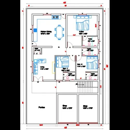

Centerline Drawing :
1. What Is a Centerline Drawing?
A centerline drawing (also called a setting-out plan) shows the exact center positions of all structural and partition walls, columns, and footings in a building.
It is used by engineers and site supervisors to mark and locate the structure accurately on the ground before starting excavation or foundation work.
👉 It acts as the reference drawing for all other construction drawings (foundation, footing, and wall layout).
📐 2. Purpose of a Centerline Drawing
- To locate footings, columns, and walls precisely on site.
- To mark intersection points (grid lines) that define the structural geometry.
- To ensure alignment and symmetry of the building.
- To minimize errors in excavation and RCC foundation placement.
- To provide reference for all vertical elements (columns, walls, etc.).
📄 3. Components Shown in a Centerline Drawing
ComponentDescriptionGrid Lines / Center LinesContinuous or dashed lines representing the center of walls and columns.Grid NamingGrids marked with numbers (1, 2, 3...) in one direction and letters (A, B, C...) in the perpendicular direction.Intersection PointsThe points where grids cross — exact center of columns or walls.Overall DimensionsTotal building width and length (outer to outer).Internal DimensionsDistance between grid lines (center to center).Column / Footing NumbersTags (e.g., C1, C2, F1, etc.) for identification.Wall Thickness NotesIndicated beside the centerline or in a note block.Reference Line / DatumOne fixed line (often along the road or boundary) from which all measurements start.North DirectionArrow showing building orientation.Level ReferenceBenchmark elevation (e.g., +0.00 = plinth level).
🧱 4. Typical Conventions Used
FeatureRepresentationCenterline TypeDashed line (--- — --- — ---) or chain lineDimensioningUsually center-to-center distancesColumn CentersMarked by intersection of two grid linesFootingsLabeled with footing number (e.g., F1, F2, etc.)OffsetsGiven from reference boundary line or road edgeWall ThicknessMentioned separately — e.g., “230 mm brick wall, centerline shown”
🧩 5. Example of Centerline Notation (Text Version)
Let’s take a small 2BHK house (30' × 40') as an example:
Grid Lines:
A, B, C, D → Along length (East-West)
1, 2, 3, 4 → Along width (North-South)

Dimensions:
Between A–B = 10’-0”
Between B–C = 12’-0”
Between C–D = 10’-0”

Between 1–2 = 10’-0”
Between 2–3 = 12’-0”
Between 3–4 = 10’-0”

Footing/Column Labels:
C1 at intersection of A1
C2 at intersection of A2
C3 at intersection of B1
...
This tells the construction team exactly where to dig and place each footing or column.
📊 6. Typical Drawing Scales
DrawingRecommended ScaleCenterline Plan (Ground Floor)1:100Foundation Centerline Layout1:50Detailed Footing Layout1:25
🧾 7. Notes on Centerline Drawing
- All dimensions are in millimeters unless otherwise mentioned.
- Verify site dimensions before marking on the ground.
- Centerline positions must be cross-checked with architectural and structural plans.
- Grid intersections are to be fixed using theodolite / total station / cross strings.
- Marked grid points should be protected with batter boards or reference pegs during excavation.
- Wall thickness should be deducted equally on both sides of centerline when setting out.
🧠 8. Field Implementation (Site Setting-Out)
Step 1: Establish the base line (reference line) using boundary or road.
Step 2: Mark perpendicular base line using 3-4-5 method or total station.
Step 3: Locate grid intersections as per drawing.
Step 4: Transfer center points to the ground using lime or string lines.
Step 5: Verify diagonal dimensions to confirm squareness.
Step 6: Fix pegs or nails at all centerline intersections.
📘 9. Reference Standards
- IS 1200 (Part 2): Measurement of Building Works
- IS 696: Code for Engineering Drawing
- NBC 2016: Building Planning and Layout
- CPWD Manual: Setting Out Procedures
1. What Is a Centerline Drawing?
A centerline drawing (also called a setting-out plan) shows the exact center positions of all structural and partition walls, columns, and footings in a building.
It is used by engineers and site supervisors to mark and locate the structure accurately on the ground before starting excavation or foundation work.
👉 It acts as the reference drawing for all other construction drawings (foundation, footing, and wall layout).
📐 2. Purpose of a Centerline Drawing
- To locate footings, columns, and walls precisely on site.
- To mark intersection points (grid lines) that define the structural geometry.
- To ensure alignment and symmetry of the building.
- To minimize errors in excavation and RCC foundation placement.
- To provide reference for all vertical elements (columns, walls, etc.).
📄 3. Components Shown in a Centerline Drawing
ComponentDescriptionGrid Lines / Center LinesContinuous or dashed lines representing the center of walls and columns.Grid NamingGrids marked with numbers (1, 2, 3...) in one direction and letters (A, B, C...) in the perpendicular direction.Intersection PointsThe points where grids cross — exact center of columns or walls.Overall DimensionsTotal building width and length (outer to outer).Internal DimensionsDistance between grid lines (center to center).Column / Footing NumbersTags (e.g., C1, C2, F1, etc.) for identification.Wall Thickness NotesIndicated beside the centerline or in a note block.Reference Line / DatumOne fixed line (often along the road or boundary) from which all measurements start.North DirectionArrow showing building orientation.Level ReferenceBenchmark elevation (e.g., +0.00 = plinth level).
🧱 4. Typical Conventions Used
FeatureRepresentationCenterline TypeDashed line (--- — --- — ---) or chain lineDimensioningUsually center-to-center distancesColumn CentersMarked by intersection of two grid linesFootingsLabeled with footing number (e.g., F1, F2, etc.)OffsetsGiven from reference boundary line or road edgeWall ThicknessMentioned separately — e.g., “230 mm brick wall, centerline shown”
🧩 5. Example of Centerline Notation (Text Version)
Let’s take a small 2BHK house (30' × 40') as an example:
Grid Lines:
A, B, C, D → Along length (East-West)
1, 2, 3, 4 → Along width (North-South)

Dimensions:
Between A–B = 10’-0”
Between B–C = 12’-0”
Between C–D = 10’-0”

Between 1–2 = 10’-0”
Between 2–3 = 12’-0”
Between 3–4 = 10’-0”

Footing/Column Labels:
C1 at intersection of A1
C2 at intersection of A2
C3 at intersection of B1
...
This tells the construction team exactly where to dig and place each footing or column.
📊 6. Typical Drawing Scales
DrawingRecommended ScaleCenterline Plan (Ground Floor)1:100Foundation Centerline Layout1:50Detailed Footing Layout1:25
🧾 7. Notes on Centerline Drawing
- All dimensions are in millimeters unless otherwise mentioned.
- Verify site dimensions before marking on the ground.
- Centerline positions must be cross-checked with architectural and structural plans.
- Grid intersections are to be fixed using theodolite / total station / cross strings.
- Marked grid points should be protected with batter boards or reference pegs during excavation.
- Wall thickness should be deducted equally on both sides of centerline when setting out.
🧠 8. Field Implementation (Site Setting-Out)
Step 1: Establish the base line (reference line) using boundary or road.
Step 2: Mark perpendicular base line using 3-4-5 method or total station.
Step 3: Locate grid intersections as per drawing.
Step 4: Transfer center points to the ground using lime or string lines.
Step 5: Verify diagonal dimensions to confirm squareness.
Step 6: Fix pegs or nails at all centerline intersections.
📘 9. Reference Standards
- IS 1200 (Part 2): Measurement of Building Works
- IS 696: Code for Engineering Drawing
- NBC 2016: Building Planning and Layout
- CPWD Manual: Setting Out Procedures.
Email : www.bechennai.com, Mobile no : 888 333 33 22.
Keywords