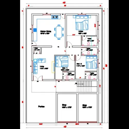
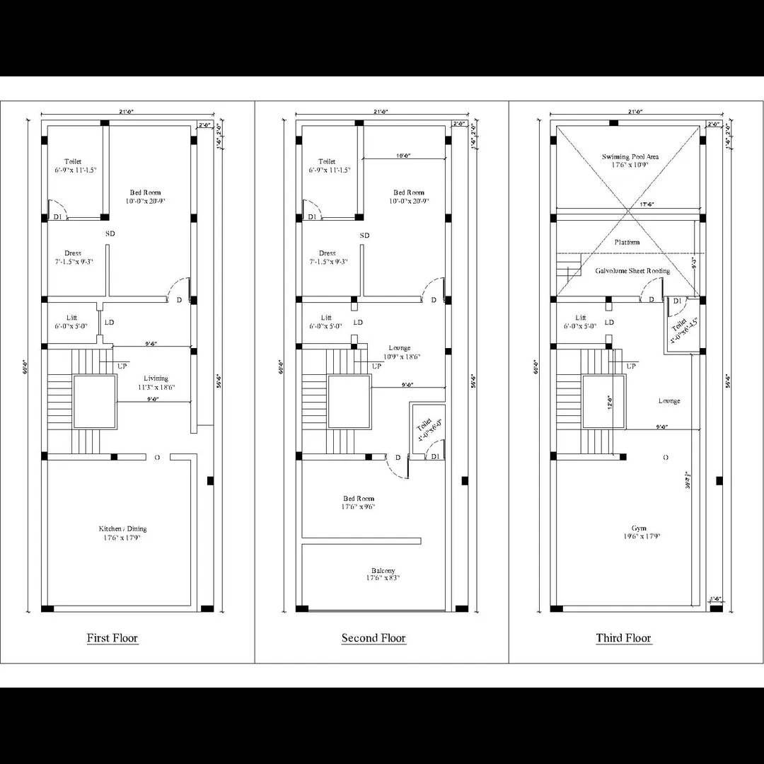
G + 2 Floor Scheme drawing :
A G+2 floor scheme drawing refers to a schematic or conceptual design of a building with:
- G = Ground floor
- +2 = Two upper floors (1st and 2nd floor)
This type of drawing is commonly used for residential buildings, small commercial structures, or apartment layouts. It's typically created for approvals, initial planning, or client presentation.
📐 Contents of a G+2 Floor Scheme Drawing
A scheme drawing for G+2 will include:
🔷 1. Site Layout / Plot Plan (if applicable)
- Plot boundaries with dimensions
- Building footprint on site
- Setbacks (front, rear, side margins)
- North direction
- Entry/exit points
- Parking (if required)
🔷 2. Floor Plans (Ground + 1st + 2nd)
Each floor plan should show:
ElementDescriptionWallsOutline of structural and partition wallsRooms with LabelsLiving, bedrooms, kitchen, toilets, etc.Doors & WindowsLocations (symbolic only, not detailed sizes)StaircaseLocation and orientationToilets/BathsMarked with basic fixturesBalconies (if any)Labeled and projected clearlyPassages/CirculationFlow between spacesDimensions (optional)Approx. room sizes (optional at scheme stage)
🔷 3. Terrace / Roof Plan
- Staircase headroom
- Lift machine room (if applicable)
- Water tanks
- Solar panel layout
- Parapet wall
🔷 4. Elevation (Front View) (Optional in scheme stage)
- Basic massing and floor levels
- No detailed materials or finishes
🔷 5. Section View (Optional)
- Shows internal height distribution
- Floor-to-floor height (usually ~3m per floor)
- Staircase section (schematic)
🔷 6. Title Block
Includes:
- Project name
- Client name
- Architect/designer
- Scale (e.g., 1:100)
- Date
- Drawing number
- Revision details (if any)
🏡 Typical Room Layout per Floor in a G+2 Residential Building
FloorPossible LayoutGround FloorParking, small 1BHK, office, or main 2BHK1st FloorLiving, 2 or 3 Bedrooms, Kitchen, Toilets, Balcony2nd FloorSimilar to 1st, or could be a duplex extension, or terrace access.
Email : www.bechennai.com, Mobile no : 888 333 33 22.
Keywords