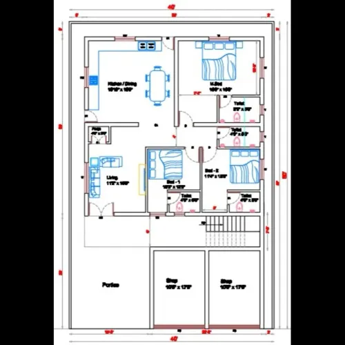
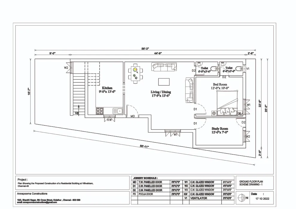
Scheme Drawing :
Here’s a detailed breakdown of what a Scheme Drawing typically includes, applicable across most engineering disciplines (e.g., mechanical, electrical, plumbing, instrumentation):
🔧 SCHEME DRAWING DETAILS
A Scheme Drawing represents the conceptual or functional layout of a system, showing how components are connected and how the system operates — not to scale, but logically accurate.
1. Title Block
Contains general drawing information:
- Project name / ID
- Drawing title (e.g., 'HVAC Scheme', 'Electrical Single Line Diagram')
- Drawing number
- Revision number and date
- Prepared by / Checked by / Approved by
- Company logo and address
2. Legend / Symbol Key
- Standardized symbols used in the drawing (based on ISO, ANSI, IEC, or company standards)
- Description of each symbol
- Line types (solid, dashed, dotted) and what they represent:
- Power lines
- Signal lines
- Control lines
- Fluid or air paths
3. System Overview
- High-level functional diagram of the system
- Flow paths (electrical, mechanical, fluid, data, etc.)
- Direction arrows indicating flow or signal direction
- Major components labeled (e.g., pumps, fans, control panels, valves, motors)
4. Device/Component Details
Each key system component should be shown with:
- Tag or identifier (e.g., MTR-101, VLV-202)
- Function block or symbol
- Basic operational info, if needed (e.g., voltage, capacity)
5. Connections & Interfaces
- Shows how each component connects within the system
- Input/output lines clearly defined
- Interdisciplinary interfaces (e.g., mechanical-electrical interface)
6. Control or Communication Logic (if applicable)
- Basic control scheme (e.g., sensor to controller to actuator)
- PLC I/O representation (in automation drawings)
- Set points, signal types (analog, digital), and conditions
7. General Notes
- Key design considerations or constraints
- Operation assumptions
- Maintenance notes (if needed)
- Reference to related standards or specifications
8. Reference Drawings
- List or callouts for related detailed drawings:
- Layouts
- Wiring diagrams
- P&IDs
- Bill of Materials (BoM)
📑 Optional Additions Based on Project/Discipline
ElementIncluded in…Flow rates / pressuresMechanical, PlumbingLoad data (e.g., kW)Electrical, HVACCommunication protocolsInstrumentation, AutomationSafety systems (e.g., ESD)Process controlRedundancy/bypass pathsCritical infrastructure
✅ Purpose of Scheme Drawing
- Preliminary design approval
- Coordination among disciplines
- Client understanding and feedback
- Basis for developing detailed engineering drawings
Email : www.bechennai.com, Mobile no : 888 333 33 22.
Keywords