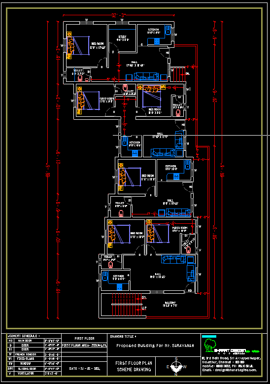
Scheme Drawing : A scheme drawing is typically a type of visual representation used to explain concepts, processes, or systems in a simplified and structured manner. It can be used in various contexts like engineering, architecture, scientific research, or even artistic projects. If you are referring to a technical drawing or diagram, it would usually include: Clear labels: Each element of the scheme is labeled with key names or references. Symbols: These represent different components (e.g., electrical components, circuit elements, or mechanical parts). Lines and Arrows: Used to indicate connections, flow, or movement. Simplified Representations: These focus on the most important aspects of the system, leaving out unnecessary detail. Examples of Different Scheme Drawings: Flowcharts (for processes): Represent steps in a process with shapes like rectangles (actions), diamonds (decisions), and arrows (flow). Circuit Diagrams (for electrical systems): Show how electrical components (like resistors, capacitors, and transistors) are connected in a circuit. Architectural Schemes: Show layout plans, elevations, and section views of buildings. Mechanical Diagrams: Show how machines or parts work, often highlighting joints, shafts, or gears. Would you like help creating a scheme drawing for a specific project or concept? Let me know what you're aiming for, and I can assist you further! www.bechennai.com. Mobile no: 888 333 33 22.

This is your website preview.
Currently it only shows your basic business info. Start adding relevant business details such as description, images and products or services to gain your customers attention by using Boost 360 android app / iOS App / web portal.
Scheme Drawing : A scheme drawing is typically a t...
2025-02-07T06:53:06
Scheme Drawing : A scheme drawing is typically a type of visual representation used to explain concepts, processes, or systems in a simplified and structured manner. It can be used in various contexts like engineering, architecture, scientific research, or even artistic projects. If you are referring to a technical drawing or diagram, it would usually include: Clear labels: Each element of the scheme is labeled with key names or references. Symbols: These represent different components (e.g., electrical components, circuit elements, or mechanical parts). Lines and Arrows: Used to indicate connections, flow, or movement. Simplified Representations: These focus on the most important aspects of the system, leaving out unnecessary detail. Examples of Different Scheme Drawings: Flowcharts (for processes): Represent steps in a process with shapes like rectangles (actions), diamonds (decisions), and arrows (flow). Circuit Diagrams (for electrical systems): Show how electrical components (like resistors, capacitors, and transistors) are connected in a circuit. Architectural Schemes: Show layout plans, elevations, and section views of buildings. Mechanical Diagrams: Show how machines or parts work, often highlighting joints, shafts, or gears. Would you like help creating a scheme drawing for a specific project or concept? Let me know what you're aiming for, and I can assist you further! www.bechennai.com. Mobile no: 888 333 33 22.
2025-02-07T06:53:06

Keywords
- wwwbechennaicom mobile
- youre aiming
- specific project
- section views
- resistors capacitors
- electrical components
- system leaving
- important aspects
- connections flow
- references symbols
- key names
- clear labels
- technical drawing
- artistic projects
- structured manner
- visual representation
- scheme drawing
- parts work
- electrical systems show
- processes represent steps
- scheme drawings flowcharts
- movement simplified representations
- mechanical parts lines
- highlighting joints shafts
- unnecessary detail examples
- explain concepts processes
Submit Your Enquiry