Scheme Drawing : A scheme drawing plan typically refers to a simplified, conceptual layout or design used to represent the arrangement of elements within a specific project. It’s often used in architecture, engineering, and construction to give a high-level overview of how spaces, systems, or components will be organized or connected. Below are some general examples of where and how scheme drawing plans are used: Types of Scheme Drawing Plans: Architectural Scheme Drawing: Purpose: Used for planning the layout of rooms, floors, and spaces in a building. Details Included: Room dimensions Placement of walls, windows, doors, and other major structural components Basic furniture or equipment layout Example: A floor plan for a house, office space, or retail environment showing how rooms or spaces are arranged. Electrical Scheme Drawing: Purpose: Represents the layout of electrical systems such as power distribution, lighting, and circuit wiring. Details Included: Locations of outlets, switches, light fixtures Power supply and circuit paths Example: Electrical plan for a building showing where electrical panels, circuits, and wiring are placed. Plumbing Scheme Drawing: Purpose: Focuses on the layout of water supply and drainage systems in a building. Details Included: Pipes, drains, vents, and water source connections Position of fixtures like sinks, toilets, showers, etc. Example: A plumbing layout for a home or building, showing water lines and drain systems. HVAC (Heating, Ventilation, and Air Conditioning) Scheme Drawing: Purpose: Illustrates the HVAC system layout, showing how air circulation, heating, and cooling elements are organized. Details Included: Ventilation ducts, exhaust points, air handling units Locations of thermostats, vents, and HVAC equipment Example: An HVAC system diagram for a commercial building. Landscape Scheme Drawing: Purpose: Used in landscape architecture to plan outdoor spaces. Details Included: Placement of trees, bushes, paths, water features, etc. Grading and drainage information Example: A garden plan or park layout showing where different plants, paths, and structures are located. Structural Scheme Drawing: Purpose: Shows the overall structural design of a building or construction project. Details Included: Foundation layout Position of load-bearing walls, beams, and columns Example: A structural plan for a building showing key load-bearing elements and materials. Land Use Scheme Drawing: Purpose: Represents the zoning and use of land in urban planning or property development. Details Included: Differentiation between residential, commercial, industrial, and green spaces Proposed developments, roads, and infrastructure Example: A zoning map for a city or neighborhood development plan. Key Elements to Include in a Scheme Drawing Plan: Title and Scale: Include the project title, scale, and date. Dimensions: Basic measurements of space, length, or size of components. Annotations: Labels for rooms, spaces, or systems to explain their function. Key/Legend: A symbol key that explains any symbols or abbreviations used in the drawing. Steps to Create a Scheme Drawing Plan: Understand the Project: Know the scope of the project, whether it's residential, commercial, industrial, or landscape. Gather Information: Get the dimensions, layout, and specifications needed to draft the scheme. Sketch the Basic Layout: Begin by sketching the overall structure or system layout on paper or using CAD (Computer-Aided Design) software. Add Key Components: Place significant features (walls, doors, windows, systems, etc.) in the design. Label & Annotate: Use labels, arrows, and notes to explain the different parts of the plan. Review and Revise: Ensure the drawing is accurate, practical, and conforms to any local building codes or regulations. Software Tools for Creating Scheme Drawing Plans: AutoCAD: Widely used for creating detailed and scalable drawings for architectural, mechanical, and electrical plans. SketchUp: A 3D modeling tool that can be used for creating simple layouts and designs. Revit: A Building Information Modeling (BIM) software used for creating detailed architectural and construction designs. Visio: A diagramming tool often used for process flows and network layouts, useful for electrical or plumbing scheme drawings. Mobile no: 888 333 33 22. www.bechennai.com.

This is your website preview.
Currently it only shows your basic business info. Start adding relevant business details such as description, images and products or services to gain your customers attention by using Boost 360 android app / iOS App / web portal.
Scheme Drawing : A scheme drawing plan typical...
2025-03-01T08:10:03
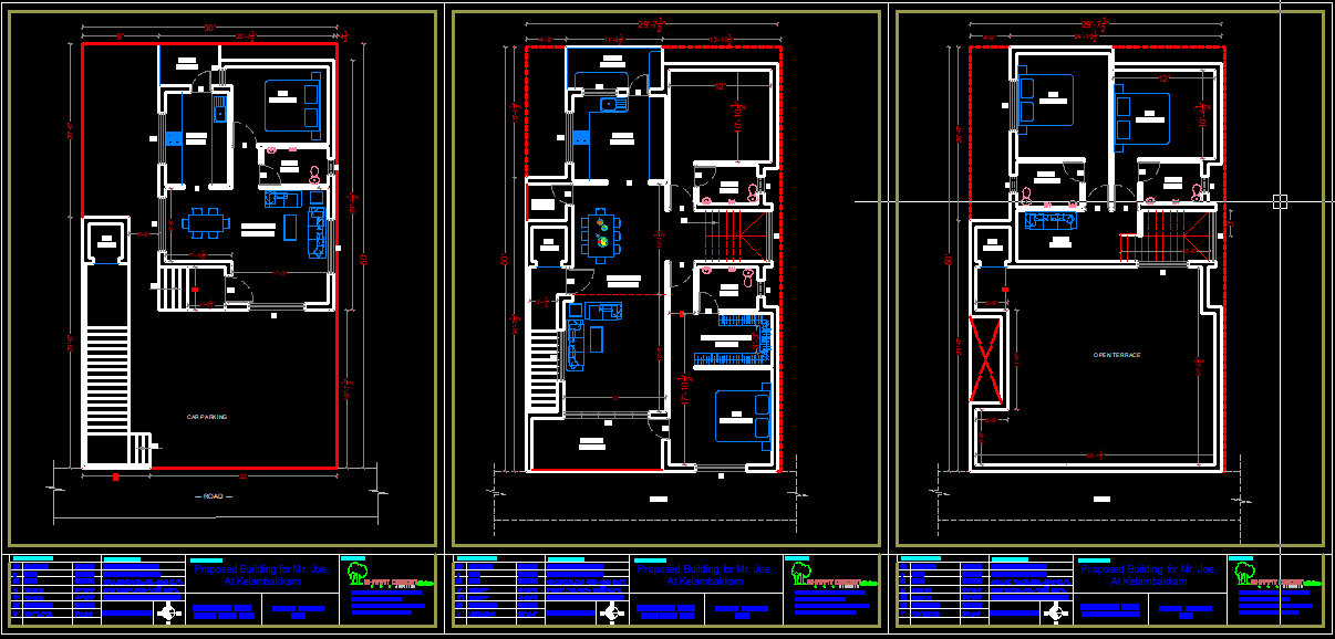
Scheme Drawing : A scheme drawing plan typically refers to a simplified, conceptual layout or design used to represent the arrangement of elements within a specific project. It’s often used in architecture, engineering, and construction to give a high-level overview of how spaces, systems, or components will be organized or connected. Below are some general examples of where and how scheme drawing plans are used: Types of Scheme Drawing Plans: Architectural Scheme Drawing: Purpose: Used for planning the layout of rooms, floors, and spaces in a building. Details Included: Room dimensions Placement of walls, windows, doors, and other major structural components Basic furniture or equipment layout Example: A floor plan for a house, office space, or retail environment showing how rooms or spaces are arranged. Electrical Scheme Drawing: Purpose: Represents the layout of electrical systems such as power distribution, lighting, and circuit wiring. Details Included: Locations of outlets, switches, light fixtures Power supply and circuit paths Example: Electrical plan for a building showing where electrical panels, circuits, and wiring are placed. Plumbing Scheme Drawing: Purpose: Focuses on the layout of water supply and drainage systems in a building. Details Included: Pipes, drains, vents, and water source connections Position of fixtures like sinks, toilets, showers, etc. Example: A plumbing layout for a home or building, showing water lines and drain systems. HVAC (Heating, Ventilation, and Air Conditioning) Scheme Drawing: Purpose: Illustrates the HVAC system layout, showing how air circulation, heating, and cooling elements are organized. Details Included: Ventilation ducts, exhaust points, air handling units Locations of thermostats, vents, and HVAC equipment Example: An HVAC system diagram for a commercial building. Landscape Scheme Drawing: Purpose: Used in landscape architecture to plan outdoor spaces. Details Included: Placement of trees, bushes, paths, water features, etc. Grading and drainage information Example: A garden plan or park layout showing where different plants, paths, and structures are located. Structural Scheme Drawing: Purpose: Shows the overall structural design of a building or construction project. Details Included: Foundation layout Position of load-bearing walls, beams, and columns Example: A structural plan for a building showing key load-bearing elements and materials. Land Use Scheme Drawing: Purpose: Represents the zoning and use of land in urban planning or property development. Details Included: Differentiation between residential, commercial, industrial, and green spaces Proposed developments, roads, and infrastructure Example: A zoning map for a city or neighborhood development plan. Key Elements to Include in a Scheme Drawing Plan: Title and Scale: Include the project title, scale, and date. Dimensions: Basic measurements of space, length, or size of components. Annotations: Labels for rooms, spaces, or systems to explain their function. Key/Legend: A symbol key that explains any symbols or abbreviations used in the drawing. Steps to Create a Scheme Drawing Plan: Understand the Project: Know the scope of the project, whether it's residential, commercial, industrial, or landscape. Gather Information: Get the dimensions, layout, and specifications needed to draft the scheme. Sketch the Basic Layout: Begin by sketching the overall structure or system layout on paper or using CAD (Computer-Aided Design) software. Add Key Components: Place significant features (walls, doors, windows, systems, etc.) in the design. Label & Annotate: Use labels, arrows, and notes to explain the different parts of the plan. Review and Revise: Ensure the drawing is accurate, practical, and conforms to any local building codes or regulations. Software Tools for Creating Scheme Drawing Plans: AutoCAD: Widely used for creating detailed and scalable drawings for architectural, mechanical, and electrical plans. SketchUp: A 3D modeling tool that can be used for creating simple layouts and designs. Revit: A Building Information Modeling (BIM) software used for creating detailed architectural and construction designs. Visio: A diagramming tool often used for process flows and network layouts, useful for electrical or plumbing scheme drawings. Mobile no: 888 333 33 22. www.bechennai.com.
2025-03-01T08:10:03
Share it on


Keywords
- rooms spaces
- spaces systems
- zoning map
- urban planning
- materials land
- cooling elements
- rooms floors
- drainage systems
- specific project
- electrical systems
- process flows
- scalable drawings
- accurate practical
- revise ensure
- plan review
- specifications needed
- dimensions layout
- drawing steps
- symbol key
- function keylegend
- structural plan
- structural design
- plants paths
- garden plan
- thermostats vents
- plumbing layout
- water supply
- circuit paths
- floor plan
- equipment layout
- general examples
- highlevel overview
- architecture engineering
- electrical plan
- scheme sketch
- scheme drawing
- network layouts
- diagramming tool
- designs revit
- architectural mechanical
- labels arrows
- system layout
- space length
- drainage information
- landscape architecture
- hvac equipment
- building showing
- creating detailed
- project title scale
- scheme drawing plans
- construction designs visio
- components annotations labels
- creating detailed architectural
- park layout showing
- local building codes
- design label annotate
- basic layout begin
- landscape gather information
- hvac system diagram
- simplified conceptual layout
- creating simple layouts
- electrical plans sketchup
- electrical panels circuits
- 3d modeling tool
- house office space
- retail environment showing
- regulations software tools
- residential commercial industrial
- loadbearing walls beams
- air circulation heating
- sinks toilets showers
- power distribution lighting
- walls windows doors
Submit Your Enquiry