Scheme Plan: Ground floor plan A Plan Scheme detailing typically refers to a comprehensive, visual representation of a building or construction project, often used in architecture, civil engineering, or urban planning. It provides specific information about the layout, design, functionality, and technical aspects of a building or development. Below, I will break down the key elements typically included in a Plan Scheme detailing, along with explanations of what each part usually entails. 1. Site Plan / Layout Plan Building Footprint: The layout of the building(s) within the plot, showing the footprint (the outer walls of the structure). Topography: The elevation and contours of the land, including slopes, hills, and drainage paths. These details are crucial for managing stormwater, foundation design, and landscaping. Access Points: Driveways, parking areas, entrances, exits, and any access points for pedestrians or vehicles. Boundaries: The property’s boundaries, indicating its size and limits. Landscape Features: Trees, shrubs, lawns, gardens, and other landscaping elements. Surrounding Infrastructure: Adjacent roads, utilities (water, gas, electricity), neighboring buildings, etc. 2. Floor Plans Room Layout: The arrangement of all rooms, hallways, staircases, and walls within the building, showing the space’s organization and functional zones. Dimensions: Each room's dimensions (length, width, and height) are shown in precise measurements. Window and Door Locations: Indicating where windows and doors are positioned, including door swings and window styles (sliding, casement, etc.). Furniture Layout (if applicable): In interior design or furniture planning, the arrangement of furniture pieces within the spaces can also be shown. 3. Elevation Plans Exterior Views: Drawings that show the building's exterior views from the front, sides, and rear. These indicate the building’s height, rooflines, windows, doors, and exterior materials. Material Specifications: Details about the materials used on the exterior, such as brick, wood, metal panels, and the style of construction. Design Aesthetic: Architectural style and visual aesthetics, showing the form, shape, and architectural features of the building. Roof Details: The shape of the roof (flat, sloped, etc.), the materials used, and any visible components like chimneys or skylights. 4. Sections and Details Vertical Cross Sections: Cut-throughs of the building that show how different parts of the building will look from a side view. These sections provide insights into structural elements, floor-to-ceiling heights, and relationships between different levels of the building. Details of Structural Elements: Close-up views of specific areas that require more information (such as window or door openings, wall junctions, roof intersections, staircases, and columns). Construction Details: Detailed drawings of how parts of the building are constructed, including floor construction, wall and roof structure, and any special building components like chimneys, elevators, or HVAC systems. 5. Electrical Layout Outlets and Switches: The location of power outlets, light switches, and other electrical devices in each room. Lighting: Placement of light fixtures, both ceiling and wall-mounted. Wiring Routes: The path for wiring or cables, including circuits, main panels, and sub-panels. Safety Elements: Electrical grounding, circuit breakers, and emergency lighting systems. 6. Plumbing Layout Water Supply Lines: Showing the routes for cold and hot water pipes, including their connections to fixtures like sinks, bathtubs, and toilets. Drainage and Waste Lines: Routes for drainpipes, sewage lines, and vents. Plumbing Fixtures: The location of all plumbing fixtures like toilets, showers, sinks, dishwashers, and washing machines. 7. HVAC (Heating, Ventilation, and Air Conditioning) Ventilation and Ductwork: The layout of the HVAC ducts, air intake, and exhaust vents for air circulation throughout the building. Heating Elements: Locations of heating systems like radiators, baseboard heaters, or underfloor heating pipes. Cooling Systems: Placement of air conditioning units, vents, and thermostats. 8. Fire and Safety Plan Exit Routes: Clearly marked emergency exits, evacuation routes, and stairwells to ensure safety in case of a fire or emergency. Fire Extinguishers: Placement of fire extinguishers, sprinkler systems, alarms, and smoke detectors. Fire Zones: Special zones for fire safety, including fireproof walls and safe areas for shelter during an emergency. 9. Structural Plans Foundations: The layout and design of the foundation, including footings, piles, or slabs, depending on the type of building and soil conditions. Columns, Beams, and Load-Bearing Walls: Locations of structural elements like columns, beams, and the layout of load-bearing walls. Load Calculations: Details on the load capacity of different structural elements, ensuring that the building can bear the expected loads (e.g., people, furniture, and equipment). Roof Structure: Detailed roof framing and support systems, including trusses, rafters, and supports. 10. Landscape and Exterior Features Landscaping Elements: The placement of trees, plants, grass, and gardens in outdoor spaces. Hardscaping: Features like driveways, sidewalks, patios, decks, retaining walls, and fences. Outdoor Amenities: Pools, outdoor kitchens, recreational areas, and lighting for external areas. 11. Site Utilities and Infrastructure Water and Sewer Lines: The placement of underground pipes for water and sewage systems, along with manholes and access points. Electrical and Communication Lines: Routing of electricity cables, telecommunication lines, and other utility systems. Stormwater Drainage: The layout of stormwater drainage systems, including gutters, drains, and retention ponds. 12. Material and Finishes Schedule Materials List: A schedule of materials to be used throughout the building, such as flooring materials, wall finishes, roofing materials, and exterior cladding. Finish Specifications: Details of the finishes, such as paint colors, textures, and surface treatments to be applied to various building components (walls, floors, windows). Example of Plan Scheme Layout A Plan Scheme typically includes multiple drawings, each focusing on a specific aspect of the design. A complete set could contain: Site plan (showing boundaries, roads, parking, and landscaping) Floor plans (showing the layout of rooms and spaces) Elevations (showing external views of the building) Sections (detailing how different parts of the building are constructed) Mechanical, Electrical, and Plumbing (MEP) plans (showing the systems within the building) Construction details (showing specific building techniques, connections, and materials) These details are typically drawn to scale and are accompanied by annotations to explain the design, materials, and methods to be used. The Plan Scheme can be digital or printed on paper and serves as the main document for construction and approval by regulatory authorities. www.bechennai.com

This is your website preview.
Currently it only shows your basic business info. Start adding relevant business details such as description, images and products or services to gain your customers attention by using Boost 360 android app / iOS App / web portal.
Scheme Plan: Ground floor plan A Plan Scheme detai...
2024-12-31T12:58:00
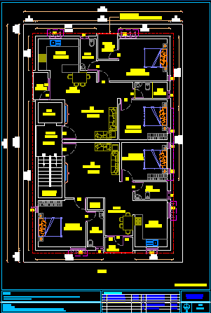
Scheme Plan: Ground floor plan A Plan Scheme detailing typically refers to a comprehensive, visual representation of a building or construction project, often used in architecture, civil engineering, or urban planning. It provides specific information about the layout, design, functionality, and technical aspects of a building or development. Below, I will break down the key elements typically included in a Plan Scheme detailing, along with explanations of what each part usually entails. 1. Site Plan / Layout Plan Building Footprint: The layout of the building(s) within the plot, showing the footprint (the outer walls of the structure). Topography: The elevation and contours of the land, including slopes, hills, and drainage paths. These details are crucial for managing stormwater, foundation design, and landscaping. Access Points: Driveways, parking areas, entrances, exits, and any access points for pedestrians or vehicles. Boundaries: The property’s boundaries, indicating its size and limits. Landscape Features: Trees, shrubs, lawns, gardens, and other landscaping elements. Surrounding Infrastructure: Adjacent roads, utilities (water, gas, electricity), neighboring buildings, etc. 2. Floor Plans Room Layout: The arrangement of all rooms, hallways, staircases, and walls within the building, showing the space’s organization and functional zones. Dimensions: Each room's dimensions (length, width, and height) are shown in precise measurements. Window and Door Locations: Indicating where windows and doors are positioned, including door swings and window styles (sliding, casement, etc.). Furniture Layout (if applicable): In interior design or furniture planning, the arrangement of furniture pieces within the spaces can also be shown. 3. Elevation Plans Exterior Views: Drawings that show the building's exterior views from the front, sides, and rear. These indicate the building’s height, rooflines, windows, doors, and exterior materials. Material Specifications: Details about the materials used on the exterior, such as brick, wood, metal panels, and the style of construction. Design Aesthetic: Architectural style and visual aesthetics, showing the form, shape, and architectural features of the building. Roof Details: The shape of the roof (flat, sloped, etc.), the materials used, and any visible components like chimneys or skylights. 4. Sections and Details Vertical Cross Sections: Cut-throughs of the building that show how different parts of the building will look from a side view. These sections provide insights into structural elements, floor-to-ceiling heights, and relationships between different levels of the building. Details of Structural Elements: Close-up views of specific areas that require more information (such as window or door openings, wall junctions, roof intersections, staircases, and columns). Construction Details: Detailed drawings of how parts of the building are constructed, including floor construction, wall and roof structure, and any special building components like chimneys, elevators, or HVAC systems. 5. Electrical Layout Outlets and Switches: The location of power outlets, light switches, and other electrical devices in each room. Lighting: Placement of light fixtures, both ceiling and wall-mounted. Wiring Routes: The path for wiring or cables, including circuits, main panels, and sub-panels. Safety Elements: Electrical grounding, circuit breakers, and emergency lighting systems. 6. Plumbing Layout Water Supply Lines: Showing the routes for cold and hot water pipes, including their connections to fixtures like sinks, bathtubs, and toilets. Drainage and Waste Lines: Routes for drainpipes, sewage lines, and vents. Plumbing Fixtures: The location of all plumbing fixtures like toilets, showers, sinks, dishwashers, and washing machines. 7. HVAC (Heating, Ventilation, and Air Conditioning) Ventilation and Ductwork: The layout of the HVAC ducts, air intake, and exhaust vents for air circulation throughout the building. Heating Elements: Locations of heating systems like radiators, baseboard heaters, or underfloor heating pipes. Cooling Systems: Placement of air conditioning units, vents, and thermostats. 8. Fire and Safety Plan Exit Routes: Clearly marked emergency exits, evacuation routes, and stairwells to ensure safety in case of a fire or emergency. Fire Extinguishers: Placement of fire extinguishers, sprinkler systems, alarms, and smoke detectors. Fire Zones: Special zones for fire safety, including fireproof walls and safe areas for shelter during an emergency. 9. Structural Plans Foundations: The layout and design of the foundation, including footings, piles, or slabs, depending on the type of building and soil conditions. Columns, Beams, and Load-Bearing Walls: Locations of structural elements like columns, beams, and the layout of load-bearing walls. Load Calculations: Details on the load capacity of different structural elements, ensuring that the building can bear the expected loads (e.g., people, furniture, and equipment). Roof Structure: Detailed roof framing and support systems, including trusses, rafters, and supports. 10. Landscape and Exterior Features Landscaping Elements: The placement of trees, plants, grass, and gardens in outdoor spaces. Hardscaping: Features like driveways, sidewalks, patios, decks, retaining walls, and fences. Outdoor Amenities: Pools, outdoor kitchens, recreational areas, and lighting for external areas. 11. Site Utilities and Infrastructure Water and Sewer Lines: The placement of underground pipes for water and sewage systems, along with manholes and access points. Electrical and Communication Lines: Routing of electricity cables, telecommunication lines, and other utility systems. Stormwater Drainage: The layout of stormwater drainage systems, including gutters, drains, and retention ponds. 12. Material and Finishes Schedule Materials List: A schedule of materials to be used throughout the building, such as flooring materials, wall finishes, roofing materials, and exterior cladding. Finish Specifications: Details of the finishes, such as paint colors, textures, and surface treatments to be applied to various building components (walls, floors, windows). Example of Plan Scheme Layout A Plan Scheme typically includes multiple drawings, each focusing on a specific aspect of the design. A complete set could contain: Site plan (showing boundaries, roads, parking, and landscaping) Floor plans (showing the layout of rooms and spaces) Elevations (showing external views of the building) Sections (detailing how different parts of the building are constructed) Mechanical, Electrical, and Plumbing (MEP) plans (showing the systems within the building) Construction details (showing specific building techniques, connections, and materials) These details are typically drawn to scale and are accompanied by annotations to explain the design, materials, and methods to be used. The Plan Scheme can be digital or printed on paper and serves as the main document for construction and approval by regulatory authorities. www.bechennai.com
2024-12-31T12:58:00

Keywords
- design materials
- building details
- chimneys elevators
- form shape
- spaces organization
- specific information
- furniture layout
- fire safety
- thermostats 8 fire
- interior design
- building showing
- typically drawn
- complete set
- specific aspect
- surface treatments
- gutters drains
- infrastructure water
- supports 10 landscape
- trusses rafters
- support systems
- people furniture
- expected loads
- load capacity
- columns beams
- slabs depending
- footings piles
- safe areas
- fireproof walls
- ensure safety
- heating systems
- sinks bathtubs
- light fixtures
- specific areas
- side view
- architectural features
- front sides
- furniture pieces
- furniture planning
- slopes hills
- structure topography
- outer walls
- technical aspects
- urban planning
- construction project
- toilets drainage
- drainage paths
- plot showing
- main document
- sewage systems
- underground pipes
- air circulation
- exhaust vents
- plumbing fixtures
- visible components
- door swings
- vehicles boundaries
- electrical devices
- roof structure
- skylights 4 sections
- sewer lines
- structural elements
- access points
- plan scheme
- building roof details
- layout design functionality
- room lighting placement
- plan scheme layout
- vents plumbing fixtures
- buildings exterior views
- special building components
- building sections detailing
- stormwater drainage systems
- wallmounted wiring routes
- hot water pipes
- constructed mechanical electrical
- access points electrical
- structural elements ensuring
- loadbearing walls locations
- floor construction wall
- precise measurements window
- rooms hallways staircases
- waste lines routes
- drainpipes sewage lines
- plan scheme detailing
- visual aesthetics showing
- air conditioning ventilation
- circuits main panels
- door locations indicating
- propertys boundaries indicating
- sections provide insights
- roof flat sloped
- communication lines routing
- regulatory authorities wwwbechennaicom
- paint colors textures
- trees plants grass
- radiators baseboard heaters
- functional zones dimensions
- architecture civil engineering
- comprehensive visual representation
Submit Your Enquiry