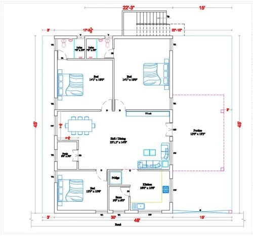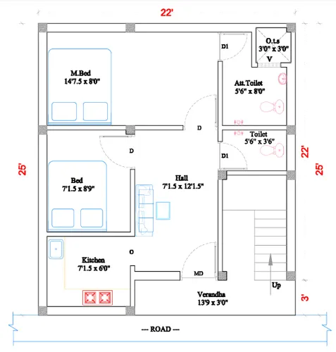
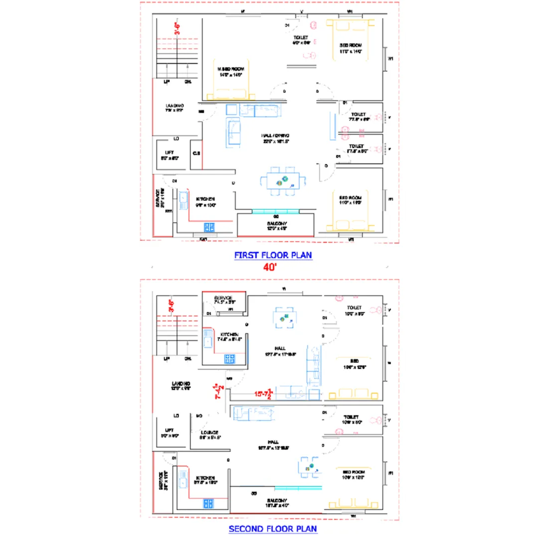
Building Scheme drawing :
A Building Scheme Drawing is a preliminary or planning drawing that shows the overall layout, arrangement, and concept of a building project before detailed construction drawings are prepared. It is commonly used in architecture, civil engineering, municipal approvals, and construction planning.
Main purpose of a Building Scheme Drawing
It helps to:
- Present the building concept
- Show room and space arrangement
- Explain building dimensions and orientation
- Obtain client approval
- Apply for local authority/municipality approval
- Guide detailed architectural and structural drawings
Typical details included
1. Site Plan
Shows:
- Plot boundaries
- Building position on land
- Road access
- Setbacks/open spaces
- Parking areas
- Drainage and utilities
2. Floor Plan
Shows:
- Room layout
- Wall positions
- Doors and windows
- Staircases
- Dimensions
- Furniture arrangement (sometimes)
3. Elevation Drawings
Shows:
- Front, rear, and side appearance
- Building height
- Exterior finishes
- Roof shape
- Architectural style
4. Section Drawings
Shows:
- Internal cut view of the building
- Floor-to-floor heights
- Foundation details
- Roof and slab levels
- Structural relationships
5. Structural Details
May include:
- Column positions
- Beam layout
- Footing sizes
- Slab thickness
- Reinforcement references
6. Electrical & Plumbing Layout
Shows:
- Switches
- Lighting points
- Water lines
- Drainage lines
- Toilet/kitchen fittings
7. Dimensions & Scale
Building drawings are normally prepared using standard scales like:
- 1:100
- 1:50
- 1:200
These help contractors accurately interpret sizes and distances.
Common drawing sheets in a scheme drawing set
A complete scheme drawing package may contain:
- Cover sheet
- Key plan
- Site layout
- Floor plans
- Elevations
- Sections
- Structural scheme
- Electrical layout
- Plumbing layout
- Door/window schedule
Software commonly used
- AutoCAD
- Revit
- SketchUp
- STAAD Pro
- ArchiCAD
Difference between Scheme Drawing and Working Drawing
FeatureScheme DrawingWorking DrawingPurposeConcept & approvalActual constructionDetail levelBasic/moderateHighly detailedUsed byClient/authorityContractors/site engineersIncludes reinforcement detailsUsually limitedCompleteConstruction-readyNoYes
Simple example
For a house project, a scheme drawing may show:
- 2 bedrooms
- Hall
- Kitchen
- Staircase
- Front elevation
- Plot setbacks
But the working drawing later adds:
- Reinforcement bars
- Beam sizes
- Electrical circuits
- Plumbing pipe routes
- Construction joints
If you want, I can also help with:
- sample building scheme drawing
- residential building plan explanation
- symbols used in drawings
- approval drawing format in Tamil Nadu
- AutoCAD scheme drawing examples
- 2D/3D scheme drawing preparation steps
Company Name : Bharat Design Seravices.
Web : www.bechennai.com.
Mobile no ; 888 333 33 22.
Keywords