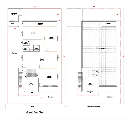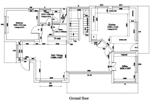
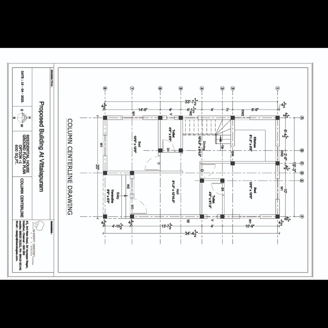
Centerline drawing : A Centerline Drawing is a foundational type of construction drawing used primarily in civil and architectural projects. It provides a simplified but precise representation of the alignment of structural elements, mainly focusing on walls, columns, foundations, and other major components using their centerlines rather than their full outlines.
🧭 What is a Centerline Drawing?
A centerline drawing shows the exact central axis of:
- Walls (internal and external)
- Columns and footings
- Beams
- Structural grids
- Roads or infrastructure in civil projects
It acts as a reference for layout planning, excavation, foundation setting, and structural coordination.
📐 Key Elements in a Centerline Drawing
1. Gridlines and Reference Lines
- Alphabetic (A, B, C...) and numeric (1, 2, 3...) gridlines.
- These define intersection points for layout and are critical for column/wall positioning.
2. Centerlines of Structural Elements
- Dashed or dotted lines showing the center of:
- Columns
- Walls
- Footings
- Beams
- Typically labeled with notations like
CLor a double dash (-- -- --).
3. Dimensions
- Overall dimensions of the structure.
- Distances between centerlines (e.g., grid spacings).
- Wall thickness or offsets from centerlines may be noted.
4. Column Layout
- Exact center points of each column marked with identifiers (e.g., C1, C2).
- Important for footing placement.
5. Foundation Plan Coordination
- Shows how the centerline layout translates to foundation positions.
- Helps in excavating and setting out footings correctly.
6. Wall Centerlines
- Used for masonry or concrete wall layouts.
- Allows accurate construction by giving fixed reference points.
7. Levels and Elevations (Optional)
- May include level indicators like:
- Ground level (GL)
- Plinth level
- Basement or slab levels
🧱 Use Cases
FieldUse of Centerline DrawingCivil EngineeringLayout of roads, retaining walls, drains, and culverts.ArchitectureWall, door, and partition layout.Structural EngineeringPositioning columns and beams with precision.Construction ExecutionOn-site layout using total stations or measuring tapes.
📝 Important Notes
- Typically provided at the early stage of the project.
- Coordinates with:
- Structural drawings
- Foundation plans
- Excavation layout
- Should be updated if there are any structural or design changes.
- Always checked for dimensional consistency with other drawings.
Email : www.bechennai.com, Mobile no : 888 333 33 22.
Keywords