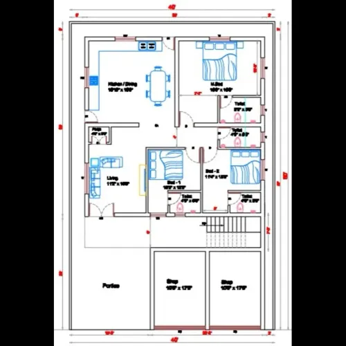
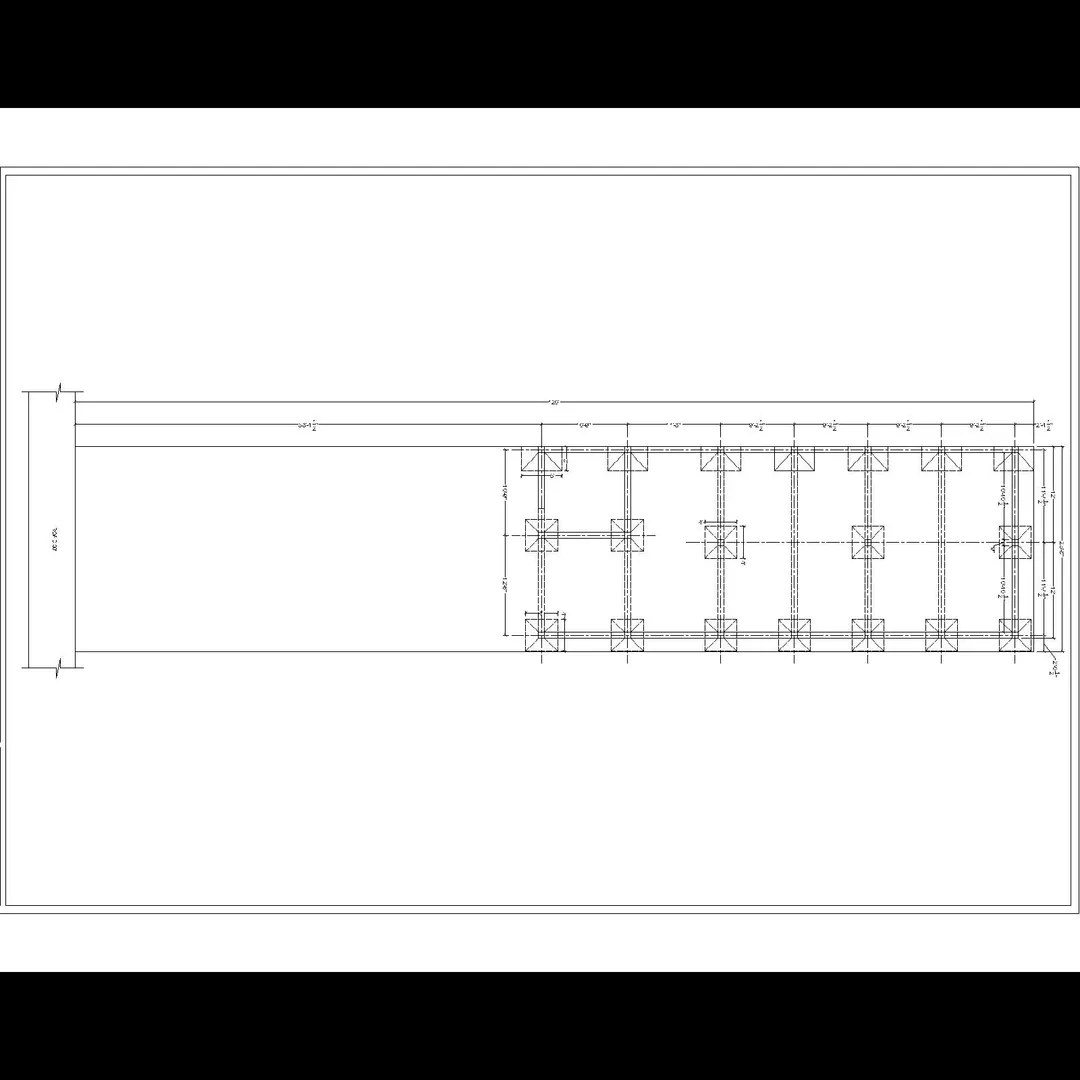
Footing Drawing :
A Footing Drawing is a critical part of a building’s structural design. It provides detailed information on the size, depth, shape, and reinforcement of the footings — the lowest structural elements that transfer loads from columns to the ground.
Here's a full breakdown of what footing drawings typically include, their purpose, and how they're interpreted in construction.
🧱 What Is a Footing Drawing?
A footing drawing is a structural drawing that shows:
- The layout of all footings under columns (plan view)
- The type and size of each footing (isolated, combined, raft, stepped)
- The reinforcement details
- The depth and elevation relative to plinth and natural ground level
- The material specifications (concrete grade, steel grade, cover)
- Sectional views of individual footings
📐 Types of Details in a Footing Drawing
Drawing ViewWhat It ShowsFooting Layout PlanPosition of each footing in plan view with grid lines and dimensions (C/C distance).Footing ScheduleTable showing types of footings with size, reinforcement, and depth for each grid location.Footing SectionCross-section of footing showing thickness, reinforcement placement, cover, and depth below ground.Column Reinforcement Over FootingStarter bars, lap length with column bars, stirrups if needed.LevelsNatural ground level (NGL), formation level, footing bottom level, plinth level.NotesMaterial specs, codes followed, bar bending instructions, concrete mix, clear cover, etc.
📊 Typical Information in a Footing Schedule
GridFooting TypeSize (L×B×D) mmMain BarsDistribution BarsCoverA1Isolated1500 × 1500 × 50012 mm @ 150 c/c12 mm @ 150 c/c50 mm
🧱 Common Types of Footings in Drawings
- Isolated Footing – For individual columns
- Combined Footing – Shared by two columns (closely spaced)
- Stepped Footing – For large loads or weak soil
- Raft / Mat Footing – Large slab under entire building area (for poor soil)
- Pile + Pile Cap Footing – For deep foundations
🔧 Typical Reinforcement Detail (for Isolated Footing)
Let’s say:
- Size: 1500 mm × 1500 mm × 500 mm depth
- Concrete Grade: M25
- Steel Grade: Fe500
- Reinforcement:
- Bottom Layer: 12 mm Ø @ 150 mm c/c both ways
- Clear Cover: 50 mm
- Starter bars for column: 16 mm dia, lap length = 50 × bar dia
📄 Example Notes in a Footing Drawing
- “All dimensions in mm unless specified.”
- “Concrete grade M25, Reinforcement Fe500.”
- “Clear cover: 50 mm (footing), 40 mm (column).”
- “Lap length for vertical bars: 50 × diameter.”
- “Footing should rest on compacted soil strata with SBC = ___ kN/m².”
- “Use anti-termite treatment below footing level.”
🏛️ IS Code References (India)
- IS 456:2000 – Plain and Reinforced Concrete
- IS 1904 – Design and Construction of Foundations
- IS 2911 – Design of Pile Foundations
- SP 34 – Detailing of Reinforcement
- IS 875 – Design loads (dead, live, seismic etc.)
📁 Want a Sample Footing Drawing?
If you share:
- The number of columns
- Their spacing/grid layout
- The soil bearing capacity (SBC)
- The building type (G+1, commercial, etc.)
I can generate a sample footing layout plan + one footing section with reinforcement for you — tailored to your needs.
Email : www.bechennai.com, Mobile no : 888 333 33 22.
Keywords