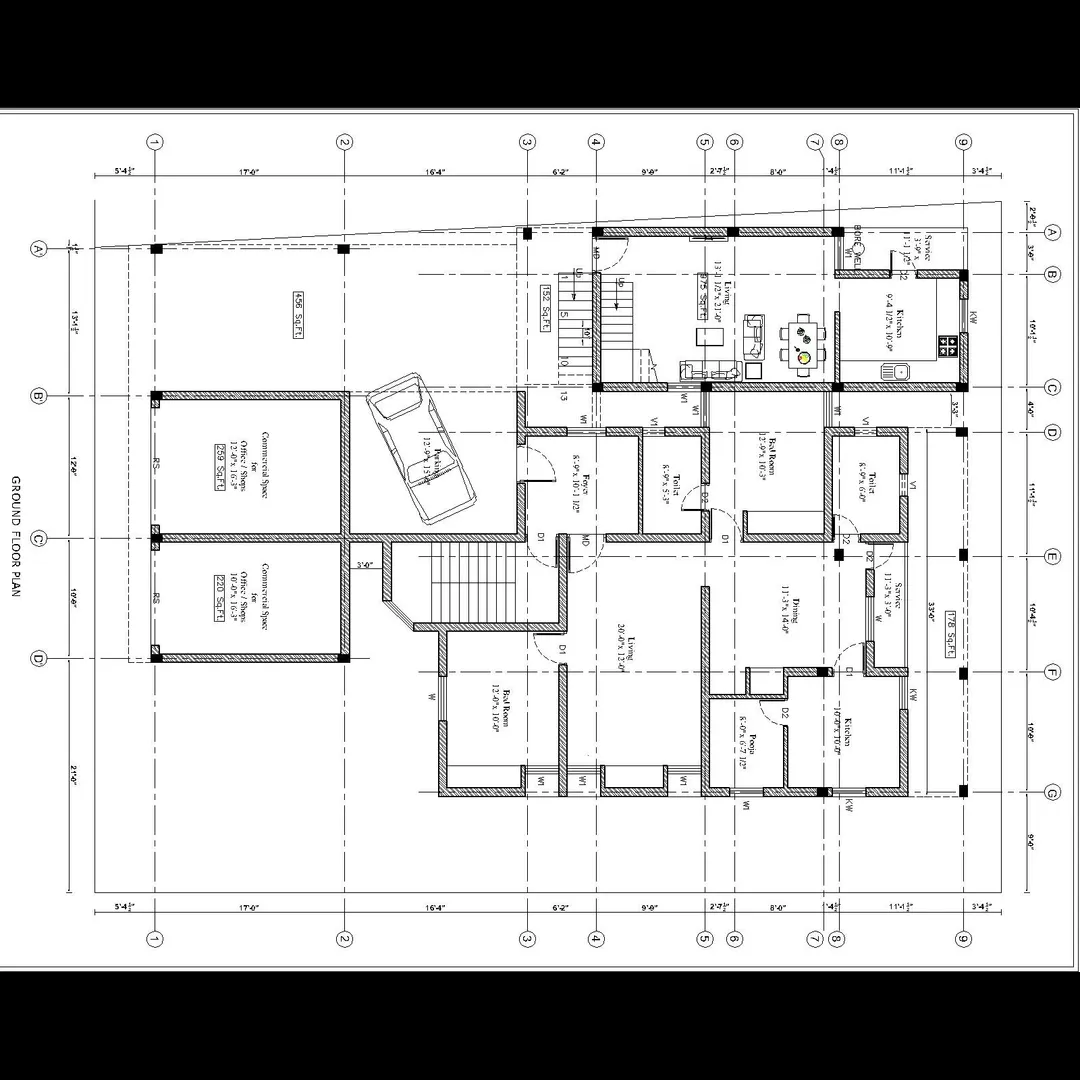
MSB Drawing Plan :
- 🏢 Multi-Storey Building (MSB) architectural & structural drawings, or
- ⚡ Main Switch Board (MSB) electrical panel layout and wiring diagram?
These two terms — MSB — are both used in engineering, so I’ll briefly explain both below. You can then confirm which one you want in full detail.
🏗️ A. MSB – Multi-Storey Building Drawing Plan Details
1. General Overview
ItemDescriptionBuilding TypeResidential / Commercial / Mixed useFloorsG+2, G+3, G+10, etc.Structural SystemRCC framed structure (columns, beams, slabs)Drawing Scales1:100 (plans, sections, elevations), 1:50 (details)
2. Types of Drawings in MSB Plan Set
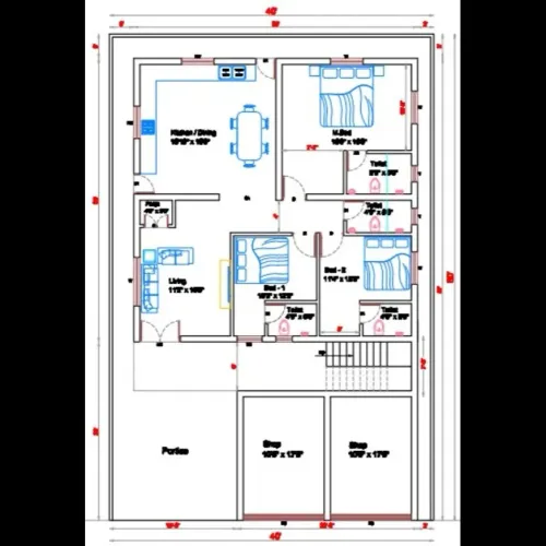
Drawing TypePurposeSite PlanShows plot boundary, roads, setbacks, and services.Typical Floor PlanShows layout of rooms, corridors, shafts, and staircases.Staircase & Lift PlanDetailed plan and section for vertical movement.Roof PlanShows terrace floor, water tanks, solar panels, etc.Sections (A–A, B–B)Vertical cut showing floor heights and structural depth.ElevationsArchitectural façade design for all sides.Structural PlansFoundation, column, beam, slab, and reinforcement drawings.Electrical LayoutSwitches, light points, DBs, conduits, and earthing.Plumbing & Sanitary PlanWater supply, waste, and rainwater lines.Fire Fighting LayoutSprinklers, hose reels, and pump room layout (for high-rise).HVAC PlanDucting, air handling units, vents, and exhausts.Area StatementFloor-wise built-up area, carpet area, FAR.
3. Structural Detailing (Typical RCC)
ElementSpecificationFoundationIsolated, combined, or raft footing depending on load.ColumnsRCC 230×450 mm to 300×600 mm (varies with height).BeamsRCC 230×300 mm to 230×450 mm.Slabs125–150 mm thick RCC.StaircaseDog-leg or open well type, riser 150 mm, tread 300 mm.Lift Pit1.5–2.0 m deep with RCC walls.
4. Architectural Elements
- Floor-to-Floor Height: 3.0–3.3 m
- Plinth Height: 0.45–0.60 m
- External Wall Thickness: 230 mm
- Internal Wall Thickness: 115 mm
- Doors/Windows: As per schedule (D1, D2, W1, etc.)
- Finishes: Floor tiles, plaster, paint, or cladding as per design
5. Essential Notes
- All RCC works to conform to IS 456:2000 and IS 875 (Part 1–5).
- Maintain proper cover: 25 mm (slab), 40 mm (beams), 50 mm (columns).
- Ensure expansion joints for buildings >45 m long.
- Fire escape stairs per NBC 2016.
- Proper lightning arrester and earthing for high-rise buildings.
⚡ B. MSB – Main Switch Board Drawing Plan Details
If by MSB you meant the Main Switch Board (in electrical engineering), here’s what’s included:
1. Components
- Incoming MCCB/ACB (Main Incomer)
- Busbar chamber (Copper or Aluminum)
- Outgoing feeders to sub-DBs
- Earthing terminals
- Volt & amp meters, indication lamps
- Control wiring and interlocks
2. Drawings Typically Prepared
DrawingDescriptionSingle Line Diagram (SLD)Shows connection between transformer, MSB, DBs, and loads.General Arrangement (GA) DrawingPhysical layout of panel (front, top, side view).Wiring DiagramInternal control wiring for interlocks, meters, and lamps.Panel ScheduleDetails of breakers, cables, and load circuits.Busbar & Cable ScheduleSize, material, and routing of busbars/cables.Earthing LayoutShows earthing pits and earth wire routing.
3. Design Details
ItemStandardIncoming Voltage415V, 3-phase, 50HzShort Circuit Rating35kA / 50kA as per fault levelEnclosurePowder-coated CRCA sheet, IP54 / IP65Busbar MaterialElectrolytic copper / aluminumCablesXLPE armored copper/aluminumStandardIS 8623 / IEC 61439
Email : www.bechennai.com, Mobile no : 888 333 33 22.
Keywords