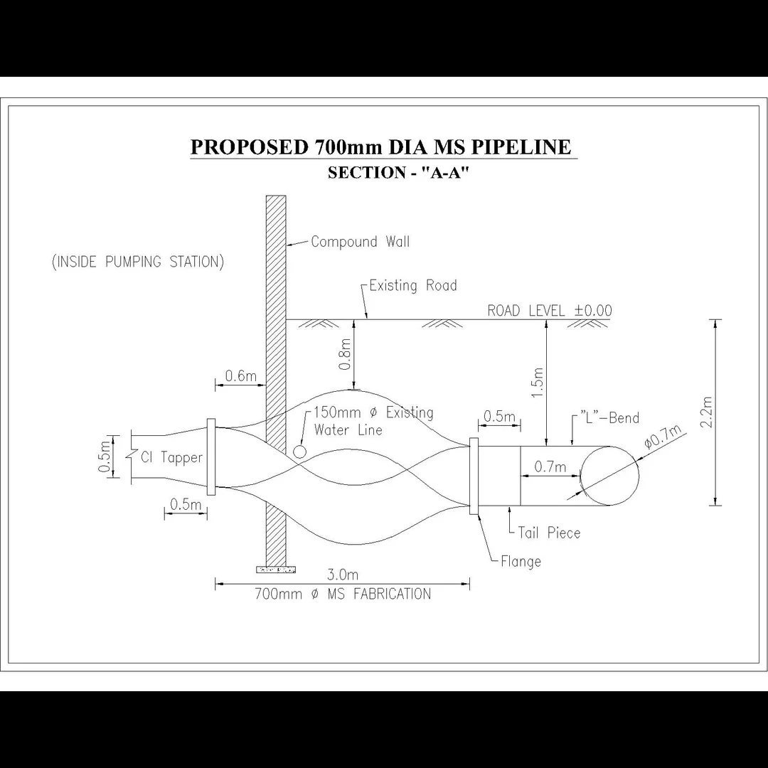
Pipe line drawing :
Here’s a general overview of pipeline drawing details in engineering:
1. Types of Pipeline Drawings
TypeDescriptionPurposePFD (Process Flow Diagram)Simplified representation showing flow paths of fluids and main equipment.To understand process sequence.P&ID (Piping and Instrumentation Diagram)Shows all process lines, instruments, valves, and control logic.For design, operation, and control reference.Piping GA (General Arrangement) DrawingPlan and elevation views showing routing, equipment, and supports.For layout and space planning.Isometric Drawing3D-type single-line drawing showing line lengths, fittings, and elevations.For fabrication and installation.Support DrawingShows pipe supports, hangers, and anchor points.For stress and installation reference.
2. Typical Details Shown in a Piping Drawing
- Line number (unique ID for each pipe)
- Pipe size and schedule
- Material specification (CS, SS, PVC, etc.)
- Flow direction
- Valves and fittings
- Insulation and heat tracing details
- Welding joints and flange types
- Elevation levels
- Support types and spacing
- Testing requirements (hydrotest pressure, etc.)
3. Common Symbols and Notations
- Lines:
- Solid = Process line
- Dashed = Instrument air / signal line
- Dotted = Electric or pneumatic connection
- Valves: Gate, Globe, Check, Ball, Butterfly — each has standard symbols (per ISA 5.1 or ISO 14617)
- Instruments: Circles with tag numbers (e.g., PT-101 = Pressure Transmitter.
Email : www.bechennai.com, Mobile no : 888 333 33 22.
Keywords