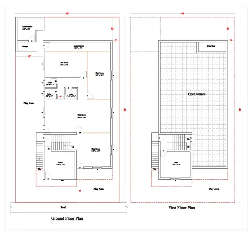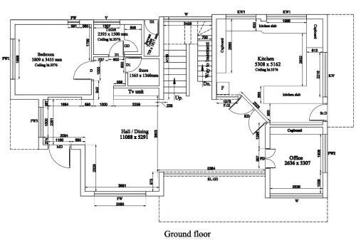
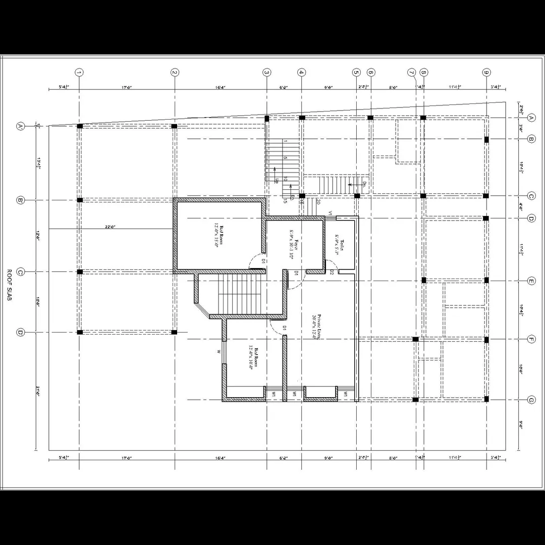
Roof Slab Plan :
A Roof Slab Plan is a critical drawing that shows the topmost RCC slab layout, including its beam arrangement, openings, slopes, drainage points, reinforcement notes, and any architectural or service features.
🏗️ 1. What Is a Roof Slab Plan?
A roof slab plan (also called an RCC slab layout or terrace slab drawing) shows:
- The layout of beams and slabs at roof level
- The direction of slab reinforcement
- Drainage slopes and outlets for rainwater
- Any openings (like staircase, skylight, water tank base, ducts, etc.)
It’s usually drawn by a structural engineer after architectural plans are finalized.
📄 2. Purpose of Roof Slab Plan
- To guide formwork and reinforcement placement during construction
- To locate drainage points and ensure proper roof slope
- To coordinate service openings (plumbing, electrical, solar, etc.)
- To check beam positions and load transfer
- To serve as the as-built reference for waterproofing, insulation, and finishing
📐 3. Components Shown in a Roof Slab Plan
ComponentDescriptionBeams (RCC)Marked by centerlines and labeled (e.g., B1, B2, etc.)Slab PanelsAreas between beams — slab numbers (S1, S2, etc.)Slab ThicknessUsually 100–150 mm (noted near each slab panel)Reinforcement DirectionArrow lines or hatch pattern showing main bar directionOpeningsDucts, skylights, staircase cutout, roof access, etc.Slope ArrowsIndicate direction of water flow toward outletsDrainage Outlets / Rainwater Pipes (RWP)Circular symbols with notes like “RWP Ø100 mm”Parapet WallTypically 1.0–1.2 m high, shown in plan viewRoof Finish LayersNotes showing waterproofing, screed, tile, etc.Column Heads / Beam IntersectionsReference points for structural coordinationDimensionsCenter-to-center between beams or wall facesNorth DirectionAlways indicated on every planLevel / Elevation MarkExample: “R.L. +10.50 m” (Roof Level)
🧱 4. Structural Details in Roof Slab Drawing
ElementTypical SpecificationSlab Thickness125 mm (residential), 150 mm (commercial)Concrete GradeM20 or M25Steel ReinforcementHYSD bars, Fe500Top Reinforcement (Temperature Bar)8 mm @ 200 mm c/c both waysBottom Reinforcement (Main Bar)10 or 12 mm @ 150 mm c/c (depending on span)Distribution Bars8 mm @ 200 mm c/cClear Cover15–20 mm (slab), 25 mm (beams)Parapet Wall115 mm thick brickwork, plastered both sidesSlope for Drainage1:40 (≈25 mm drop per meter) toward outlets
🧾 5. Typical Drawing Notes on Roof Slab Plan
General Notes:
- All dimensions are in millimeters unless otherwise specified.
- Reinforcement bars shall be as per IS 456:2000 & IS 2502.
- Concrete cover to be maintained as per IS standards.
- Roof slope 1:40 towards rainwater outlets.
- Waterproofing to be carried out before finishing.
- Rainwater pipes shall not be less than 100 mm diameter.
- Coordinate with electrical and plumbing drawings for openings.
- Levels marked are with respect to +0.00 (plinth level).
📊 6. Scales Used
DrawingRecommended ScaleRoof Slab Layout1:100Reinforcement Detailing1:50 or 1:25Rainwater Pipe Layout1:100Parapet Detail Section1:20
🧰 7. Supporting Details / Sections
A roof slab plan is usually accompanied by:
- Cross section through slab and parapet
- Typical beam-slab junction detail
- Rainwater outlet detail
- Waterproofing layer detail (bitumen membrane / chemical coating)
- Tile finish / insulation detail
🌧️ 8. Example (Text Layout)
For a 30’×40’ single-storey house:
Slab No. S1 = 125 mm thick RCC slab
Beam B1, B2, B3, B4 forming boundary
Slope arrows directed toward 3 Rainwater Outlets (RWP Ø100 mm)
R.L. +10.50 m (roof level)
Parapet wall 230 mm thick × 1.0 m high
Main reinforcement direction: along 30’ span
Top temperature reinforcement perpendicular to main bars
Opening for staircase: 2.0 m × 3.0 m near southwest corner
Email : www.bechennai.com, Mobile no : 888 333 33 22.
Keywords