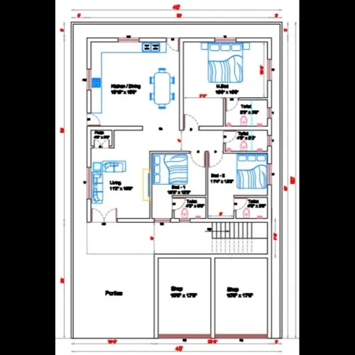
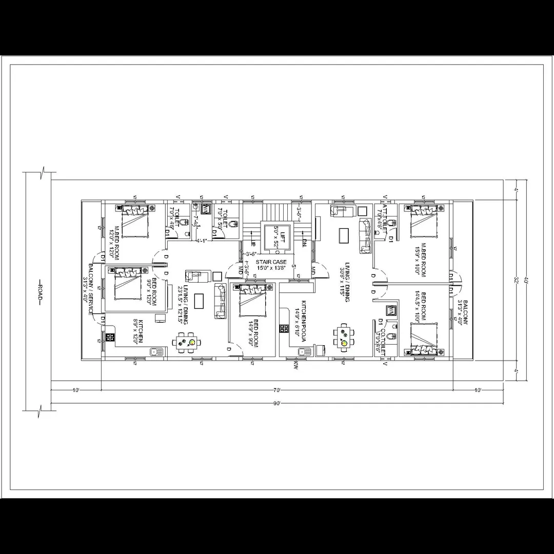
Scheme drawing :
A Scheme Drawing (also called a Schematic Drawing) is a conceptual-level drawing used in architecture, civil engineering, and MEP services to illustrate the design intent, layout, and interrelationships between different components of a system or structure — without construction-level detail.
📌 What Is a Scheme Drawing?
A scheme drawing shows the general layout, functional flow, and connectivity of systems (plumbing, electrical, structural, etc.) for coordination and early-stage planning.
It’s used as a communication tool between architects, engineers, clients, and contractors before final working drawings are created.
📐 Key Elements of a Scheme Drawing
ElementDescriptionTitle BlockProject title, client, drawing title (“Scheme Drawing”), drawing number, date, revision, scale.Symbols & LegendsElectrical/plumbing/mechanical symbols with a legend/key for easy interpretation.Lines & ArrowsRepresent flow of water, electricity, data, air, etc. (not to scale).Functional ZonesDifferent areas (e.g., dining, stage, lobby) marked with simple shapes.Direction & OrientationNorth arrow, elevation references, or flow direction arrows.Basic DimensionsApproximate or center-to-center spacing (not exact construction sizes).Notes & RevisionsDesign assumptions, material specifications, revision history, and annotations.
🧰 Types of Scheme Drawings
TypeDescriptionArchitectural Scheme DrawingGeneral layout of rooms/zones (without walls/sections detailed).Structural SchemeShows grid layout, column locations, beam span directions, slab types.Plumbing (PHE) SchemeShows water supply and drainage flow, tank locations, pipe routing concept.Electrical SchemeSLD (Single Line Diagram), light points, power socket layout, panel boards.HVAC SchemeDuct routing, AHU locations, return/exhaust air flows, cooling zones.Fire Safety SchemeHydrant lines, sprinkler zones, smoke detector locations, fire exits.
🏗️ Example – Plumbing Scheme Drawing Includes:
- Water source (e.g., borewell, municipal)
- Overhead tank (OHT) and underground sump (UGT)
- Supply lines to kitchens, toilets, hand wash
- Drainage pipe flows (soil pipe, waste pipe)
- Manhole layout (not exact depth/detail)
- Rainwater harvesting layout
- Pipe diameters (tentative), material types (e.g., PVC, GI)
💡 Example – Electrical Scheme Drawing Includes:
- Incoming supply from transformer or EB connection
- LT panel location
- DBs (Distribution Boards) on each floor
- Cable routing (conceptual path)
- Lighting zones
- Emergency backup connections (DG sets, UPS)
- Tentative load chart (sometimes)
📏 Not Drawn to Construction Scale
- Scheme drawings are usually not to scale (or at most indicative scale like 1:100 or 1:200)
- Dimensions and details are approximated to communicate design strategy
- Exact measurements come later in working drawings
🧯 Compliance & Reference Codes (India)
DisciplineCodeArchitecturalIS 962:1989PlumbingIS 1172:1993ElectricalIS 732:1989FireNBC 2016 – Part 4, IS 2190HVACASHRAE standards (optional), NBC Part 8StructuralIS 456, IS 875, SP 34 (for detailing)
🧾 Example Notes Found on Scheme Drawings
- “This schematic is for coordination purposes only.”
- “Pipe sizes and locations are indicative. Refer detailed services drawings for execution.”
- “All services to be coordinated at site before execution.”
- “All levels and dimensions are to be verified on site.”
Email : www.bechennai.com, mobile no : 888 333 33 22.
Keywords