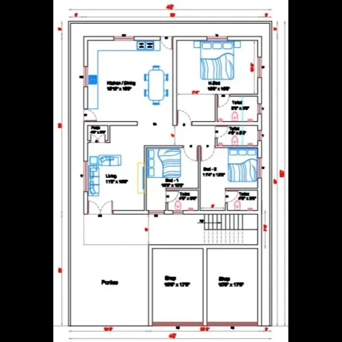
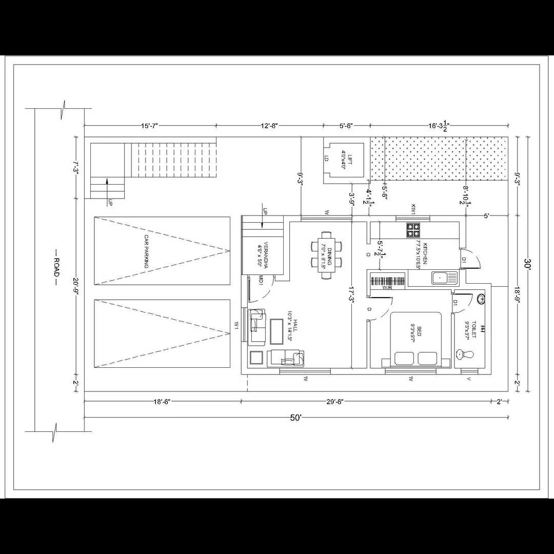
Scheme drawing :
A Scheme Drawing (also called a schematic drawing) is a preliminary, simplified layout used across architecture, civil, structural, and MEP services to show the basic design concept and functional layout of a system, space, or building — before detailed construction drawings are made.
📌 Purpose of a Scheme Drawing
- To visualize the initial concept and spatial relationships
- To show functional flow (e.g., people, water, air, electricity)
- To coordinate between disciplines (architecture, structural, MEP, etc.)
- For client approvals, internal design discussions, and early budgeting
- Often used for regulatory approvals before working drawings
📐 Contents of a Scheme Drawing
SectionWhat It IncludesTitle BlockDrawing title, project name, scale (if any), date, designer, revision numberLayout PlanSchematic layout of rooms, zones, or systems — shown with simple outlines and labelsLegend & SymbolsSymbols used for systems (electrical, plumbing, HVAC, etc.) with a clear legendFlow DirectionArrows or lines showing the direction of service or movement (water, people, air)Notes / AnnotationsClarifications, assumptions, design limitations, materials, etc.North ArrowFor orientation (especially in architectural and site drawings)ScaleUsually not to scale (NTS) or a small scale like 1:100 or 1:200Zones/FunctionsSpaces labeled according to function — e.g., kitchen, toilet, hall, office, etc.ConnectivitySchematic links between systems (e.g., electrical lines, plumbing paths, duct routes)
📂 Types of Scheme Drawings by Discipline
1. Architectural Scheme Drawing
- Room layout & zoning
- Entry/exit & circulation path
- Tentative furniture layout
- Functional area relationships
2. Structural Scheme Drawing
- Column positions and grid lines
- Beam direction and spans
- Load transfer paths (basic)
- Slab type indication
3. Plumbing Scheme (PHE)
- Water supply lines (from source to fixtures)
- Drainage layout (soil/waste pipes)
- Tank locations (OHT, UGT)
- Pipe sizes (tentative) and flow direction
4. Electrical Scheme Drawing
- Single Line Diagram (SLD)
- Distribution Boards (DBs)
- Cable paths, switch/socket locations
- Generator/UPS integration
5. HVAC Scheme
- Duct routing (supply/return air)
- Ventilation/exhaust paths
- AC unit placement (split/ducted)
- Fresh air intake and exhaust points
6. Fire Fighting Scheme
- Hydrant points, hose reels, extinguishers
- Sprinkler zoning (if applicable)
- Smoke detectors, alarm panels
- Escape routes and fire exits
🧾 Typical Notes Found on Scheme Drawings
- “This drawing is schematic and not to scale.”
- “All layouts subject to change after site verification.”
- “Final pipe routing to be confirmed with detailed drawings.”
- “Refer structural & architectural drawings for coordination.”
- “All symbols are indicative. Refer legend for details.”
📊 Common Symbols in Scheme Drawings
SymbolMeaning●Light point⎔Switch⇢Flow arrow (fluid/electricity)⬛DB (Distribution Board)🝆Fire extinguisher▭Sink/wash basin⎔ + ↯Electrical outlet
(These are schematic only — actual symbols follow IS/IEC standards.)
📏 Example Scheme Drawing Scales
Drawing TypeSuggested ScaleFloor layout (basic)1:100 / 1:200Electrical/MEP schematicsNTS (Not to Scale)Site layout1:500 or 1:1000HVAC duct layout1:100 (if schematic)
🛠️ Standards Used
- IS 962 – Code of Practice for Architectural Drawings
- IS 2065 / IS 1172 – Plumbing schematics
- IS 732 – Electrical wiring practices
- NBC 2016 – National Building Code (all disciplines)
- ASHRAE / ISHRAE – HVAC (optional for HVAC schemes)
- NFPA / IS 2190 – Fire protection layouts
🧱 Scheme Drawing Example – For a Marriage Hall
AreaDetails Shown in Scheme DrawingMain HallShape, entrance, seating layout (not furniture details)StagePosition, access routes, AV point (if any)Dining HallFlow direction, access to kitchenKitchenCooking, prep, dishwashing zonesToiletsApproximate number and locationCirculationEntry/exit flow arrowsParkingLayout if included in scheme plan.
Email : www.bechennai.com, Mobile no : 888 333 33 22.
Keywords