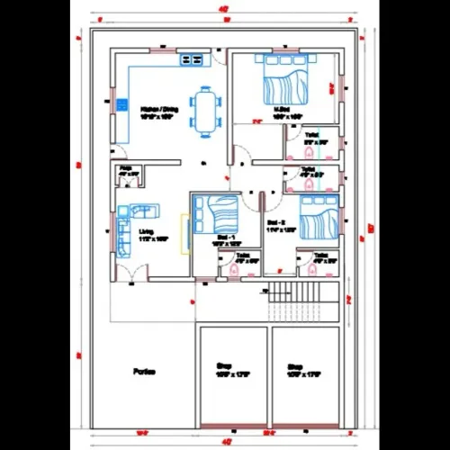
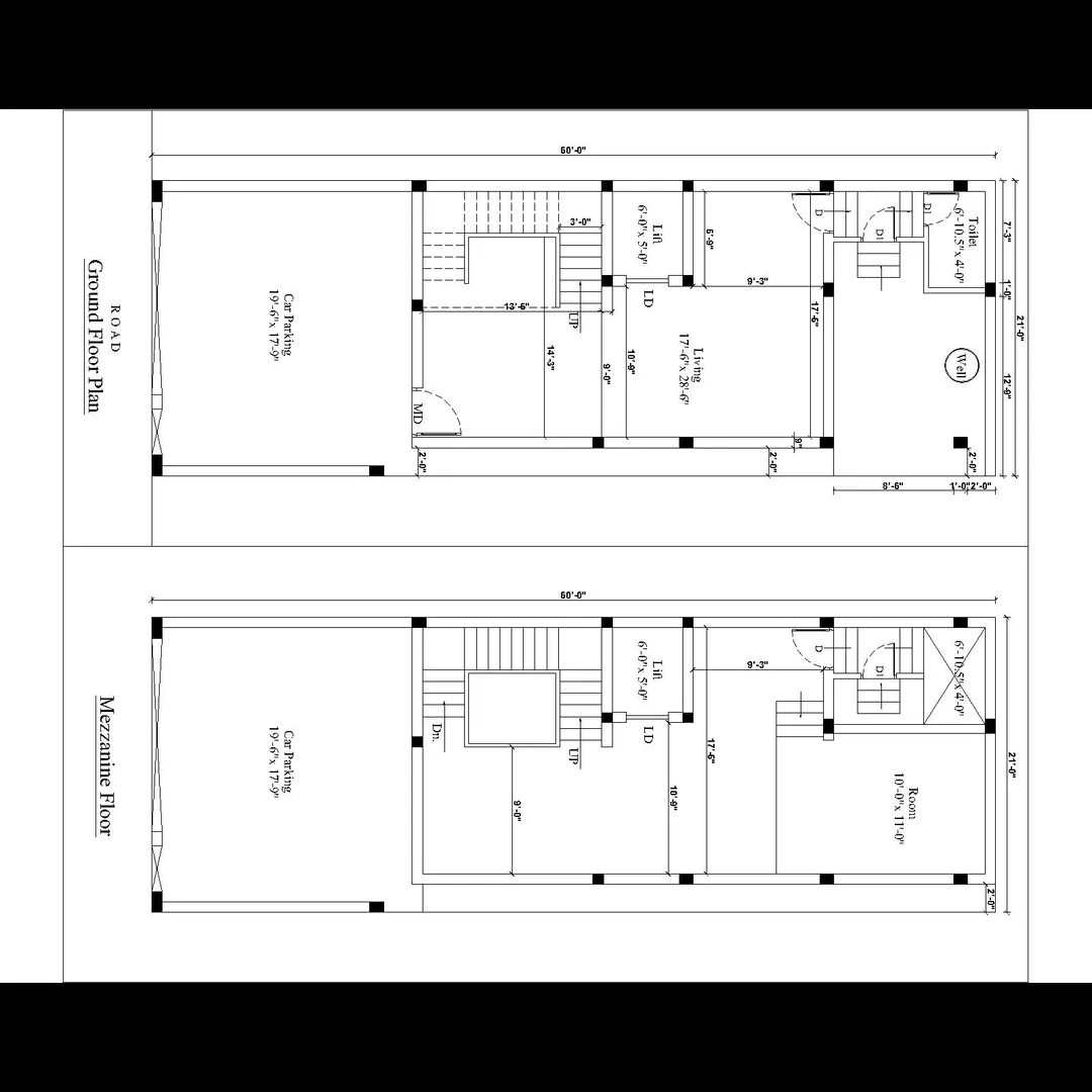
Scheme drawing :
A Scheme Drawing is a simplified, conceptual representation of a design or system, primarily used in the early stages of a project to convey ideas, layout, and functionality without going into full technical or construction-level detail.
🔍 Definition:
A Scheme Drawing shows the overall arrangement or functional layout of a project (building, infrastructure, system, etc.) and is used for:
- Initial client presentations
- Planning approvals
- Design coordination
- Zoning and circulation analysis
🏗️ Where Scheme Drawings Are Used:
FieldUse of Scheme DrawingArchitectureBasic floor plans, elevations, building massingUrban PlanningLand use zones, roads, parks, infrastructure layoutElectricalWiring diagrams, single-line diagramsMechanical/PlumbingPiping layouts, HVAC zonesCivil EngineeringRoad alignment, drainage layoutTerrace/Building PlanHeadroom, tank position, open areas, lift room
📐 Typical Contents of a Scheme Drawing
FeatureDescriptionSimplified shapesTo represent rooms, areas, or equipmentBasic dimensionsOnly key measurements or overall sizesZoning/Color codingTo represent function (residential, commercial, etc.)Labels/AnnotationsIdentify key componentsNorth arrowIndicates orientationLegendExplains symbols usedNot to scale or rough scaleOften not accurate to detailTitle blockProject info, client, date, drawing number, etc.
📄 Examples of Scheme Drawings:
- Architectural Building Layout
- Room layout
- Circulation paths
- Entry/exit points
- Service cores (lift/staircase)
- Site Layout Scheme
- Plot boundaries
- Road networks
- Amenity zones
- Drainage and service lines
- Terrace Scheme Drawing
- Water tank locations
- Lift machine room
- Staircase headroom
- Solar panel layout
- Parapet wall outline
✅ Benefits of Scheme Drawings
- Quick to produce and revise
- Helps in early-stage decisions
- Useful for non-technical stakeholders
- Supports authority submissions
- Cost-effective before detailed drawings.
Email : www.bechennai.com, Mobile no : 888 333 33 22.
Keywords