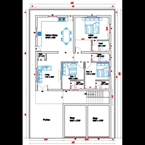
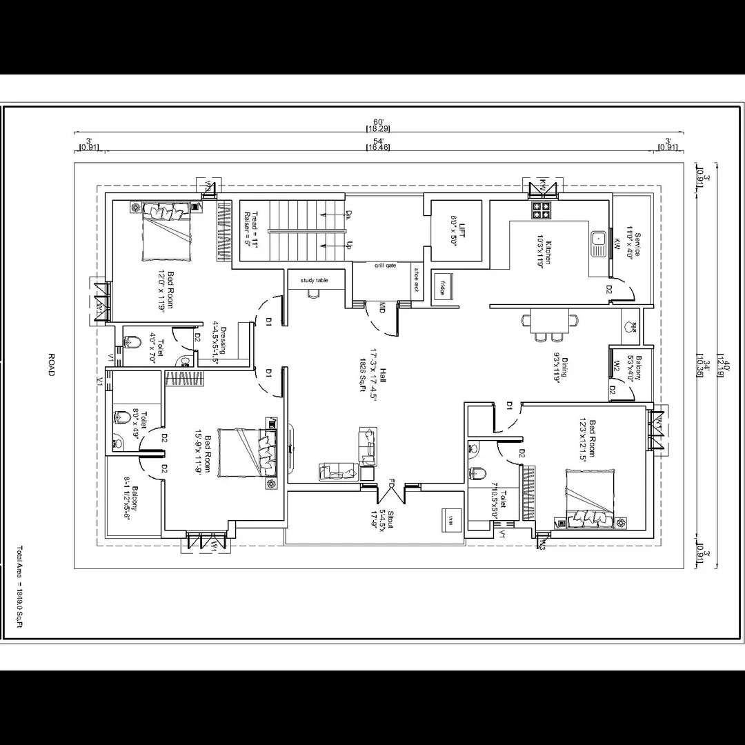
Scheme drawing :
Scheme Drawing (or schematic drawing) is a preliminary conceptual layout used in architecture, civil, MEP, or structural engineering to show how different components of a system relate to each other before detailed drawings are prepared.
It’s often the first stage of design documentation and is widely used in building planning, water supply, electrical systems, drainage, fire safety, and structural layouts.
🧾 What is a Scheme Drawing?
A Scheme Drawing is a conceptual or simplified representation that illustrates the layout, function, and connection of systems or structural elements, without going into detailed construction-level specifications.
It is meant to communicate design intent — not precise geometry.
📐 Types of Scheme Drawings by Discipline
DisciplineWhat the Scheme Drawing ShowsArchitecturalRoom layout, access routes, functional zones (e.g. residential, commercial, service areas).StructuralColumn layout, beam framing scheme, slab types, structural grid.PlumbingWater supply routes, drainage lines, pipe sizing, water tanks, sewage connections.ElectricalMain distribution, switchboards, circuits, light and power point locations.Fire SafetySprinkler layout, hydrant lines, smoke detectors, escape paths.HVACDuct routing, equipment positions, airflow paths.
📄 Key Elements of a Scheme Drawing
ElementDescriptionTitle BlockProject name, drawing title, scale, date, revision number, designer.Symbols & LegendsGraphical symbols for valves, outlets, columns, switches, etc., with a legend.Line DiagramsSingle lines representing flow of water, electricity, air, or forces.Flow DirectionsArrows showing the direction of flow or operation.Zones / SectionsSegregation into logical areas (e.g. electrical zones, fire zones).NotesAssumptions, standards followed, and clarifying text.
📊 Example: Scheme Drawing for Plumbing System
- Overhead tank (OHT) shown on terrace
- Downpipes going vertically along shafts
- Branch lines feeding kitchen, toilet, wash area
- Symbols for valves, taps, meters
- Arrows for water flow direction
- Pipe sizes written as 25 mm, 32 mm, etc.
- Waste and soil pipes shown in different colors or line types
🏗 Example: Structural Scheme Drawing
- Grid layout: Columns placed with grid references (A1, B2…)
- Beam spans shown between columns
- General sizes (e.g., 230×300 mm beams)
- Notes like “all slabs to be 150 mm thick RCC unless noted”
- No detailed bar bending shown — just layout and connectivity
📌 Why Scheme Drawings Are Important
- Concept Approval: Helps clients and engineers understand the system early on.
- Coordination: Between disciplines (e.g. plumbing + electrical) to avoid clashes.
- Design Basis: Used to prepare detailed working drawings later.
- Budgeting: Gives rough idea of materials and costs.
- Permits: Used for municipal approvals in early design stages.
📚 Standards Followed
- IS 962:1989 – Code of practice for architectural and building drawings
- IS 2065 / 1172 – Water supply layouts
- IS 732 – Electrical wiring
- NFPA / NBC – Fire schemes
- IS 875 / 456 – Structural schemes
Email : www.bechennai.com, Mobile no : 888 333 33 22.
Keywords