TWO-WHEELER MACHINE DRAWING — FULL PLAN DETAILS
Machine drawings for a two-wheeler can be divided into:
A. Assembly Drawings (Complete Vehicle)
B. Sub-Assembly Drawings (Engine, Chassis, Suspension, etc.)
C. Component (Part) Drawings
Below is a structured guide to all details normally included.
1. ASSEMBLY DRAWING DETAILS
A. Typical Views Required
- Front View
- Side View (Right/Left Elevation)
- Top View
- Isometric View (optional but helpful)
- Sectional View through engine or chassis (if needed)
B. Major Components Shown in Assembly:
- Chassis / Frame
- Front Fork & Suspension
- Rear Swing Arm & Suspension
- Engine Assembly
- Fuel Tank
- Handlebar Assembly
- Seat Assembly
- Exhaust System
- Braking System
- Front disc/drum
- Rear disc/drum
- Transmission
- Chain/Belt drive
- Gearbox
- Wheels & Tyres
- Electrical Components
- Battery
- Headlight, indicators, tail lamp
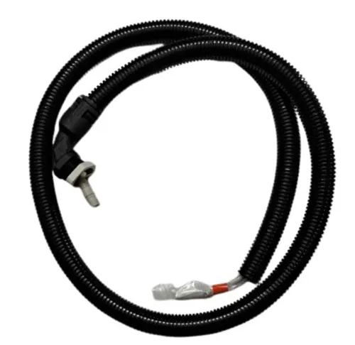
- Wiring harness route
- Footrests, pedals, stands
C. Assembly Drawing Details Must Include:
- Balloon numbering for all parts
- Title block with specifications
- Section lines (if cut views)
- Notations for:
- Wheelbase
- Overall length
- Overall height
- Ground clearance
- Seat height
- Turning radius
- Material indications (optional)
2. SUB-ASSEMBLY DRAWING DETAILS
These are drawn separately for clarity. Key sub-assemblies:
A. Engine Assembly Drawing
Shows:
- Cylinder head
- Cylinder block
- Piston + rings
- Connecting rod
- Crankshaft
- Camshaft & timing chain
- Carburetor/Fuel injection
- Crankcase & covers
- Cooling system (air fins or radiator)
- Gearbox (if integrated)
Include:
- Sectional cut through piston–cylinder
- Dimensions (bore × stroke)
- Part numbers
- Tolerances fits (H7/g6, etc.)
- Surface finish (Ra values)
B. Frame / Chassis Drawing
Includes:
- Tube/profile dimensions
- Welding locations
- Mounting points for engine, fuel tank, seat
- Fork angle (rake), trail
- Swingarm pivot
- Reinforcement gussets
- Material specs (e.g., mild steel ERW tube)
C. Front Fork & Suspension
Details:
- Telescopic fork tubes
- Spring preload
- Damper rod
- Oil levels
- Steering stem bearings
- Triple clamp (upper & lower yokes)
D. Rear Suspension / Swing Arm
Shows:
- Swing arm length
- Pivot dimensions
- Shock absorber mounting
- Axle slot
- Chain/belt guides
E. Braking System
- Disc rotor diameter
- Caliper mounting
- Drum brake sectional view
- Brake pedal linkage
- Master cylinder position & routing
F. Wheel Assembly
- Hub
- Rim
- Spokes (if applicable)
- Tyre specs
- Axle & bearings
3. INDIVIDUAL PART DRAWINGS (Manufacturing Drawings)
Each critical part must have its own drawing.
Part Drawings Include:
- Orthographic views (Front, Top, Side)
- Sectional view (if required)
- Exact dimensions
- Tolerances & fits
- GD&T symbols
- Material specifications
- Surface finish symbols
- Heat treatment notes (for components like crankshaft, camshaft)
- Quantity (for BOM)
Examples:
- Piston
- Crankshaft
- Gear components
- Camshaft
- Axles
- Nuts/Bolts (special)
- Handlebar
- Brake lever
- Chain sprocket
Email : www.bechennai.com, Mobile no : 888 333 33 22.
Keywords