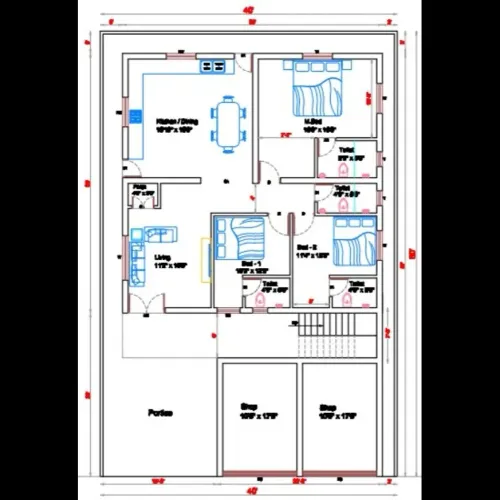
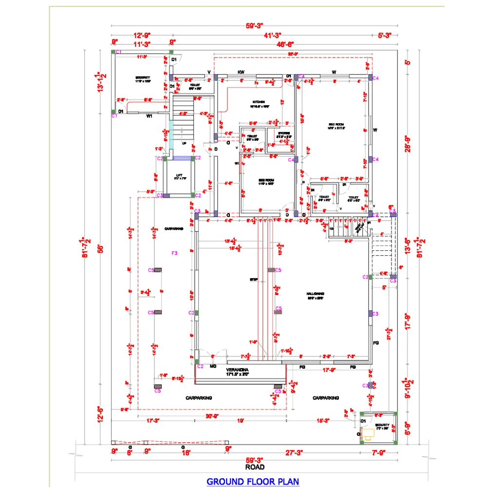
Working drawing building plan :
Working drawings (also called construction drawings) provide exact, scaled, and fully dimensioned information required for building on site.
1. GENERAL INFORMATION ON A WORKING DRAWING SHEET
A. Title Block
Contains:
- Project name
- Client name
- Architect/firm name & registration
- Drawing title (e.g., “GROUND FLOOR PLAN – WORKING DRAWING”)
- Drawing number
- Scale (e.g., 1:50, 1:100)
- Date & revision history
- Sheet size (A1/A2/A0 etc.)
B. Notes
- General construction notes
- Material specifications
- Abbreviation list
- Legends for symbols
2. ESSENTIAL ELEMENTS OF A WORKING FLOOR PLAN
A. Accurate Wall Representation
- Wall thickness clearly shown (e.g., 150mm, 230mm, 300mm)
- Structural vs non-structural walls differentiated
- Detailed column grid + column schedule ref.
B. Complete Dimensions
Working drawings are fully dimensioned, including:
- Overall building length & width
- Internal room dimensions
- Wall-to-wall distances
- Door & window locations and sizes
- Clear opening sizes
- Floor-to-floor height (noted or referenced to sections)
- Setbacks from site boundaries (if included)
Dimensions typically include baseline, running, and opening dimension strings.
C. Doors and Windows
Each door/window has:
- Symbol (D1, D2, W1, W2, V, etc.)
- Size (e.g., 900×2100mm)
- Hinges & swing direction
- Sill height (for windows)
Usually provided via a Door/Window Schedule on a separate sheet.
3. ROOM DETAILS
Each room label includes:
- Room name (e.g., MASTER BEDROOM)
- Floor level reference (e.g., FFL ±0.00)
- Floor finish type (tiles, wood, carpet)
- Area (optional at working-drawing level)
4. STRUCTURAL DETAILS SHOWN ON PLAN
A. Columns
- Column numbers (e.g., C1, C2)
- Column centerlines
- Column sizes (e.g., 300×450mm)
B. Beams (if shown on plan)
- Beam centerlines
- Beam numbers referencing structural drawings
C. Load-bearing walls & shear walls
Clearly marked.
5. SERVICE DETAILS
A. Electrical (if included on the same sheet or separate)
- Switchboard location
- Lighting points
- Power outlets
- AC points
- Conduit paths
- Circuit numbers (E1, E2 etc.)
B. Plumbing / Sanitary
- Water supply lines
- Drainage lines & slopes
- Manholes with numbering
- Plumbing fixture exact locations
- Floor trap positions & diameters
C. HVAC (if applicable)
- Duct routes
- Ventilation points
- AC units, drainage lines
6. MATERIAL AND CONSTRUCTION SPECIFICATIONS
Working plan includes notes on:
- Wall type (brick, block, RCC)
- Floor finish materials
- Roof/ceiling structure
- Waterproofing areas
- Insulation details (if required)
- Exterior finish (plaster, paint, cladding)
7. SECTIONS AND ELEVATION REFERENCES
Floor plan must reference:
- Section cut symbols (A–A, B–B)
- Elevation directions (E1, E2 etc.)
Sections typically show:
- Foundation depth
- Floor height
- Roof height
- Slab thickness
- Stair profiles
8. ADDITIONAL WORKING DRAWINGS (Usually Separate Sheets)
- Foundation plan
- Column layout plan
- Beam layout
- Slab reinforcement plan
- Roof plan
- Terrace/roof drainage plan
- Toilet/kitchen detailed layouts
- Staircase detailed drawings
- Joinery details (doors/windows)
- Electrical layout
- Plumbing layout
- Elevations (front, rear, left, right)
- Sections (longitudinal & cross)
- Site plan
SAMPLE WORKING PLAN SYMBOLS
D1  – Door, 900×2100 mm
W2  – Window, 1200×1500 mm
CL  – Centerline
FFL – Finished Floor Level
SILL – Window Sill Height
MH  – Manhole
FT  – Floor Trap
Ø   – Diameter
↑   – Direction of elevation/section
IF YOU WANT, I CAN CREATE:
✓ A sample working drawing in text / diagram style
✓ A full working-drawing checklist for your project
✓ A CAD-ready layout plan description
✓ A complete set for a specific building (house, office, shop, school, etc.)
Email : www.bechennai.com, mobile no : 888 333 33 22.
Keywords